
Compound insulation-based low-sense busbar

A low-inductance busbar and composite insulation technology, which is applied in the direction of insulated cables, insulated conductors, conductors, etc., can solve the problems of low-inductance busbar design, high cost, and rapid aging of the insulation layer

Inactive Publication Date: 2011-07-20
CHINA ELECTRIC POWER RES INST +1
View PDF5 Cites 5 Cited by
  • Summary
  • Abstract
  • Description
  • Claims
  • Application Information

AI Technical Summary

Problems solved by technology

[0003] Although some existing low-sensitivity busbars are compact in structure and beautiful in appearance, they can meet the requirements of specific application environments to a certain extent, but there are some deficiencies, such as serious partial discharge caused by high voltage, poor heat dissipation due to large current flow, and poor insulation layer. Fast aging, high requirements and high cost of lamination process for insulating layer and copper row
There are also some low-sensitivity busbars with poor design, when the voltage is higher than 2KV, it is difficult to work for a long time

Method used


Image

  • Compound insulation-based low-sense busbar
  • Compound insulation-based low-sense busbar
  • Compound insulation-based low-sense busbar

Examples


Embodiment 1

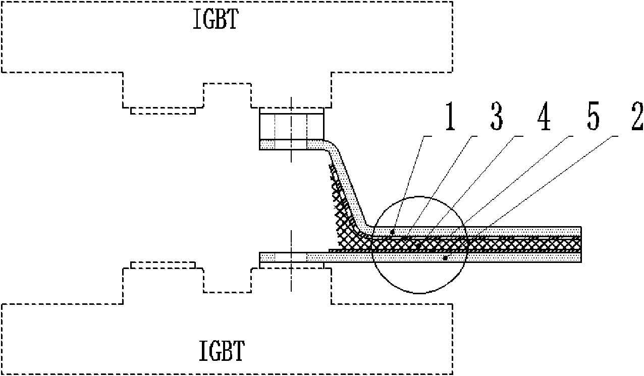
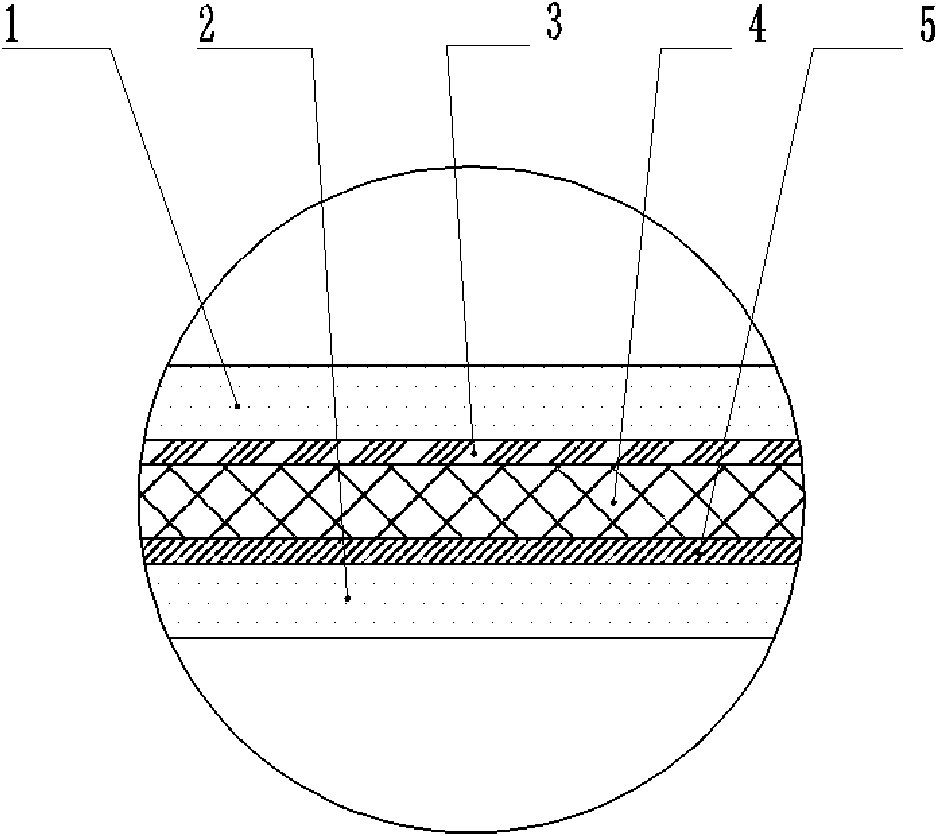
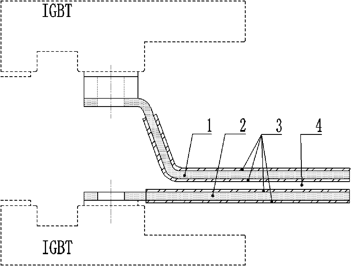
[0020] The low-inductance busbar based on composite insulation in this embodiment, such as Figure 1-3 Including copper row 1, copper row 2, insulating layer 3, insulating layer 4 and insulating layer 5 formed by orderly stacked multi-layer structure, wherein the orderly stacked arrangement is the outermost of the low-sensitivity bus bar is copper bar 1 and copper bar 2. The insulating layer 3, the insulating layer 4 and the insulating layer 5 are arranged in sequence among them.

[0021] The material of insulating layer 3, insulating layer 4 and insulating layer 5 is a combination of gas and solid insulating materials.

[0022] The insulating layer 4 is made of self-healing insulating material to prolong the service life of the busbar.

[0023] The copper bar 1 and the copper bar 2 are connected to the terminals of the power electronic device by means of bolt fastening, and the contact surface between the copper bar and the connecting terminal is nickel-plated to reduce the ...

Embodiment 2

[0027] The low-sensitivity busbar based on composite insulation in this embodiment includes a multi-layer structure formed by orderly stacking and arrangement of copper bar 1, copper bar 2, insulating layer 3, insulating layer 4 and insulating layer 5, wherein orderly stacking The outermost sides of the low-sensitivity busbars are arranged as copper bars 1 and 2, and insulating layers 3, 4, and 5 are arranged in sequence between them.

[0028] The material of the insulating layer 3, the insulating layer 4 and the insulating layer 5 is a solid insulating material.

[0029] The material of the insulating layer 4 is an insulating material with long-term corona resistance, so as to weaken the partial discharge phenomenon of the busbar.

[0030] The copper bar 1 and the copper bar 2 are connected to the terminals of the power electronic device by bolt fastening, and the connecting terminals are treated with silver plating to reduce the contact resistance.

[0031] The copper bar 1...


PUM


Abstract

The invention relates to a compound insulation-based low-sense busbar. The compound insulation-based low-sense busbar is characterized by comprising a multi-layer structure which is formed by laminating and arranging a copper bar (1), a copper bar (2), an insulating layer (3), an insulating layer (4) and an insulating layer (5) sequentially. The structure greatly reduces the local release amount between the copper bars, effectively solves the radiating problem of the busbar, and has the characteristics of convenience for processing and manufacturing, low cost, high flexibility and high adaptability.

Description

technical field [0001] The invention relates to power electronic devices, in particular to a low-sensitivity busbar with composite insulation. Background technique [0002] With the rapid development of power electronic devices, the voltage level and current level continue to increase. The 3.3kV high-power IGBT has been widely used in the field of converters, and the 6.5kV high-power IGBT has also begun to face engineering applications. During the rapid turn-on and turn-off process, both ends of the power electronic device withstand high instantaneous overvoltage, and the large distributed inductance may cause device insulation breakdown and reduce the reliability of equipment operation. How to reduce the distributed inductance of the conductive loop by rationally arranging the bus bars is one of the important issues that have attracted much attention in the design of the converter. [0003] Although some existing low-sensitivity busbars are compact in structure and beautif...

Claims


Application Information

Patent Timeline
IPC IPC(8): H01B7/02H01R13/02H01R13/03
Inventor 李强贺之渊栾洪洲李云鹏易荣
Owner CHINA ELECTRIC POWER RES INST
Learn More