
Direct current bus quick discharge circuit of explosion-proof converter

A DC bus, discharge circuit technology, applied in the direction of emergency protection circuit devices, circuit devices, emergency protection circuit devices for limiting overcurrent/overvoltage, etc. Large and other problems, to achieve high work stability and reliability, enhance maintenance and repair efficiency, and reduce system costs

Inactive Publication Date: 2011-07-20
LIAONING RONGXIN EXPLOSION PROOF ELECTRICAL TECH
View PDF5 Cites 8 Cited by
  • Summary
  • Abstract
  • Description
  • Claims
  • Application Information

AI Technical Summary

Problems solved by technology

[0002] After the traditional explosion-proof converter is powered off, the DC bus voltage is discharged by the voltage equalizing resistor or the low-resistance circuit on the auxiliary power supply board. Because the impedance of the discharge circuit is large, the discharge time will be very long, which often affects the equipment. The maintenance time cannot meet the site requirements
Moreover, since the resistor is always connected in parallel to both ends of the DC bus, the resistor is large in size and generates a large amount of heat, which brings inconvenience to the installation and heat dissipation of the system, especially in the underground environment of coal mines. The stored energy drops below 0.2mJ within 15 minutes

Method used


Image

  • Direct current bus quick discharge circuit of explosion-proof converter
  • Direct current bus quick discharge circuit of explosion-proof converter

Examples


Embodiment Construction

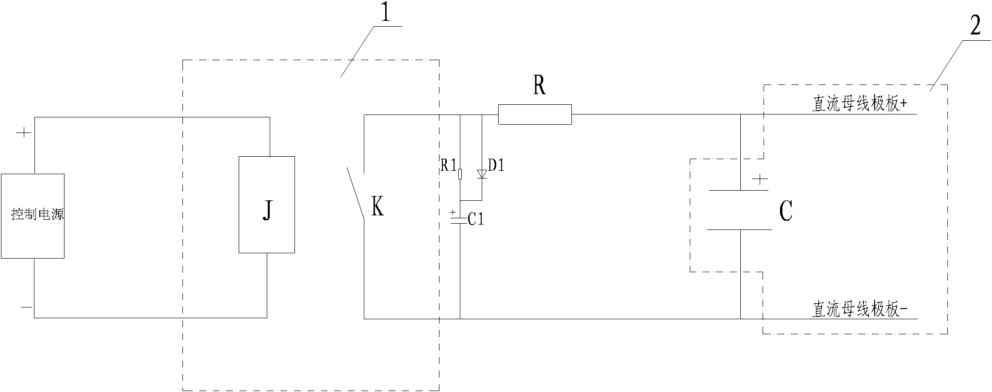
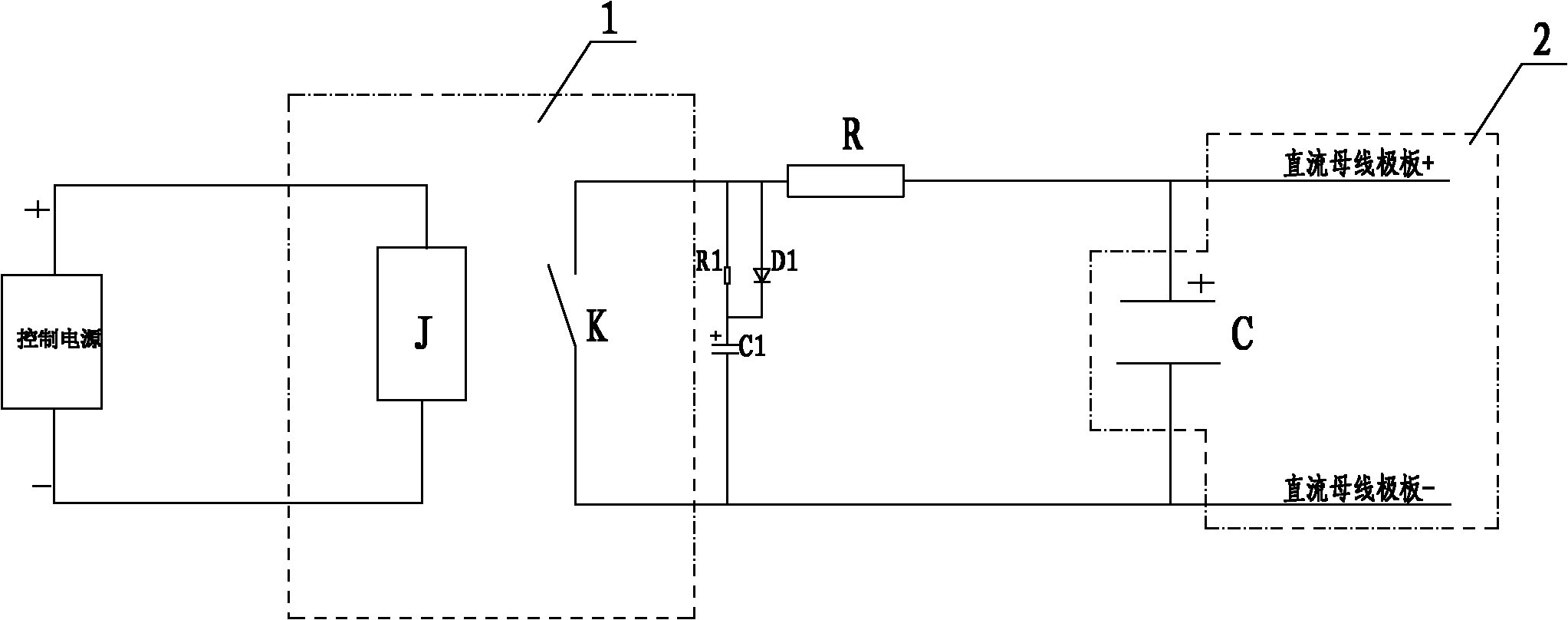
[0014] See figure 1 , Explosion-proof converter DC bus fast discharge circuit, including control power supply (including AC and DC), controllable switching device 1, power discharge resistor R, RCD resistance-capacitance absorption circuit. The controllable switch device 1 may choose a relay, a contactor, a thyristor, and the like. The control power supply is connected to the control terminal J of the controllable switching device, and the power discharge resistor R is connected in series with the contact switch K of the controllable switching device and connected to the positive terminal of the DC bus plate supported by a large capacitor C that needs to be discharged. Negative ends.

[0015] The RCD resistance-capacitance absorption circuit is composed of a resistor R1, a diode D1, and a capacitor C1. After the resistor R1 is connected in parallel with the diode D1, it is connected in series with the capacitor C1, and is connected to both ends of the contact switch K of the...


PUM


Abstract

The invention relates to a direct current bus quick discharge circuit of an explosion-proof converter. The circuit comprises a control power supply, a controllable switch type device, a power discharge resistor and an RCD (Residual Current Device) resistance-capacitance absorbing loop, wherein the control power supply is connected with the control end of the controllable switch type device; the power discharge resistor is connected in series with a contact switch of the controllable switch type device and then is connected to the positive end and the negative end of a direct current bus pole plate which is required to be discharged and comprises a high capacitance support; and the RCD resistance-capacitance absorbing loop is connected in parallel to two ends of the contact switch of the controllable switch type device. After a system is powered down, on and off of the contact switch of the controllable switch type device are controlled by controlling power-on and power-down of the control end of the controllable switch type device, so that quick discharge of a direct current bus capacitor is realized. The circuit has the advantages that energy stored by the direct current bus capacitor can be quickly reduced to below 0.2mJ in 15 minutes; the system has high working stability, reliability and safety; the maintenance efficiency and the repair efficiency of the system are increased; the volume of the equipment is reduced; and the system cost is reduced.

Description

technical field [0001] The invention relates to the technical field of direct current discharge after the equipment is powered off, and relates to a fast discharge circuit for a direct current bus of an explosion-proof converter. Background technique [0002] After the traditional explosion-proof converter is powered off, the DC bus voltage is discharged by the voltage equalizing resistor or the low-resistance circuit on the auxiliary power supply board. Because the impedance of the discharge circuit is large, the discharge time will be very long, which often affects the equipment. The maintenance time cannot meet the site requirements. Moreover, since the resistor is always connected in parallel to both ends of the DC bus, the resistor is large in size and generates a large amount of heat, which brings inconvenience to the installation and heat dissipation of the system, especially in the underground environment of coal mines. The stored energy drops below 0.2mJ within 15 ...

Claims


Application Information

Patent Timeline
Patent Type & Authority Applications(China)
IPC IPC(8): H02H9/04
CPCH02H7/122
Inventor 陈寄园孟军郑忠明车前里阎鑫昌鲁俊娄聪何晓然
Owner LIAONING RONGXIN EXPLOSION PROOF ELECTRICAL TECH
Learn More