
Boiler structure

A boiler and furnace technology, applied in the field of boiler structure, can solve the problems of increased friction loss components, worsened flow stability, and increased power of feed pump power auxiliary equipment, etc., to achieve the effect of reducing pressure loss and improving flow stability

Active Publication Date: 2011-07-20
MITSUBISHI HEAVY IND LTD
View PDF6 Cites 0 Cited by
  • Summary
  • Abstract
  • Description
  • Claims
  • Application Information

AI Technical Summary

Problems solved by technology

[0008] However, since the above-mentioned prior art has difficulties in optimizing the inner diameter of the boiler evaporator tube and managing the pressure loss, the increase in the pressure loss of the boiler evaporator tube increases the power of auxiliary equipment such as the power of the feed water pump.
The increase in power of such auxiliary equipment is the cause of the increase in the size of the boiler plant, and it is also the cause of the increase in operating costs, so there is still room for improvement.
[0009] In addition, since boiler evaporator tubes are difficult to optimize the inner diameter of the tube and manage the pressure loss, when the water in the tube expands due to temperature rise, the flow velocity increases and the friction loss component of the pressure loss increases.
Since the flow stability deteriorates due to the increase of such frictional loss components, there is room for improvement
[0010] Furthermore, in the case of uniformly increasing the inner diameter of the tube and lowering the overall flow velocity, it is effective to reduce the frictional loss component of the pressure loss and improve the flow stability and natural circulation characteristics. However, considering the In the actual situation of such supercritical pressure once-through boilers with different heat loads and distances in the height direction, increasing the inner diameter of the tube will naturally meet the limit.

Method used


Image

  • Boiler structure
  • Boiler structure
  • Boiler structure

Examples


Embodiment Construction

[0021] Hereinafter, one embodiment of the boiler structure of the present invention will be described with reference to the drawings.

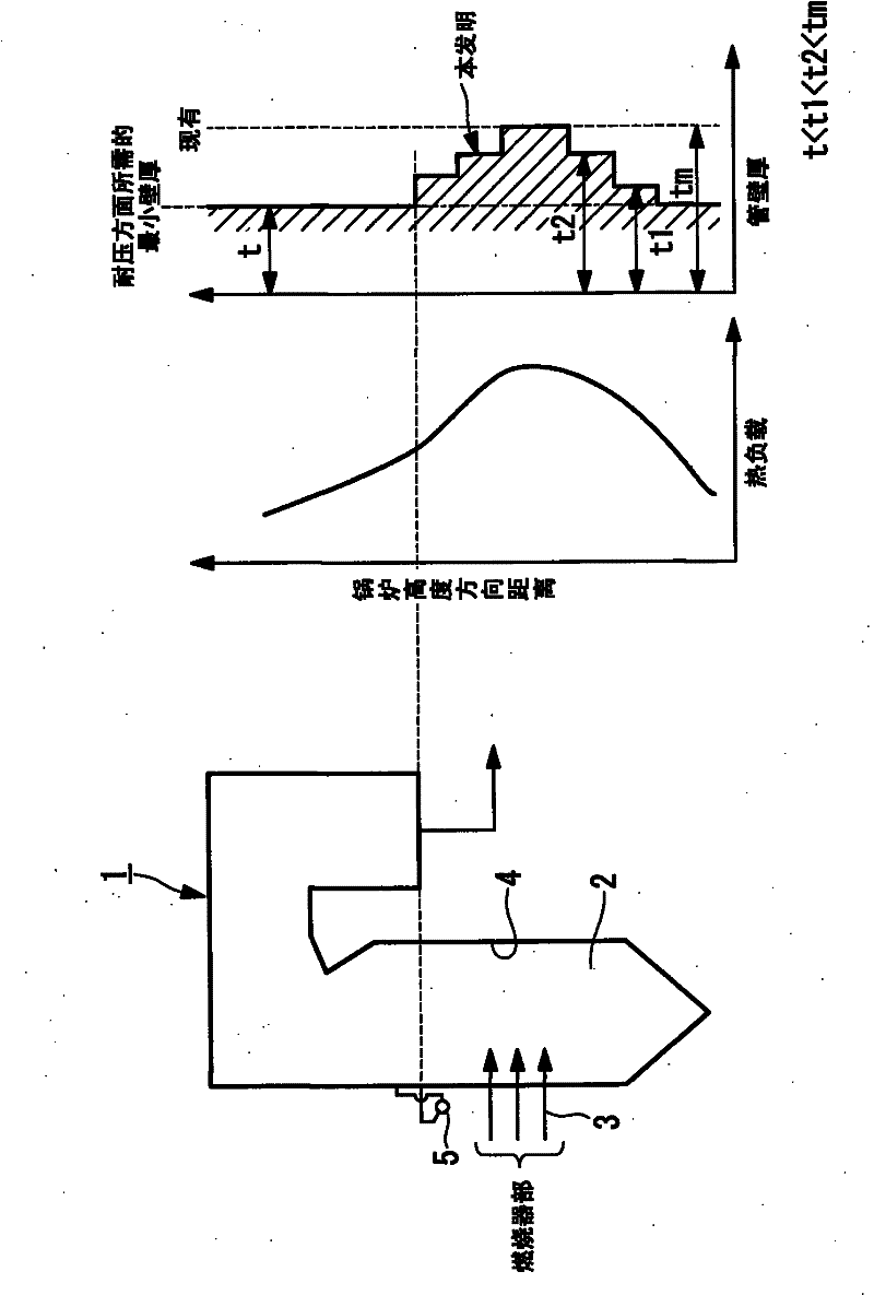
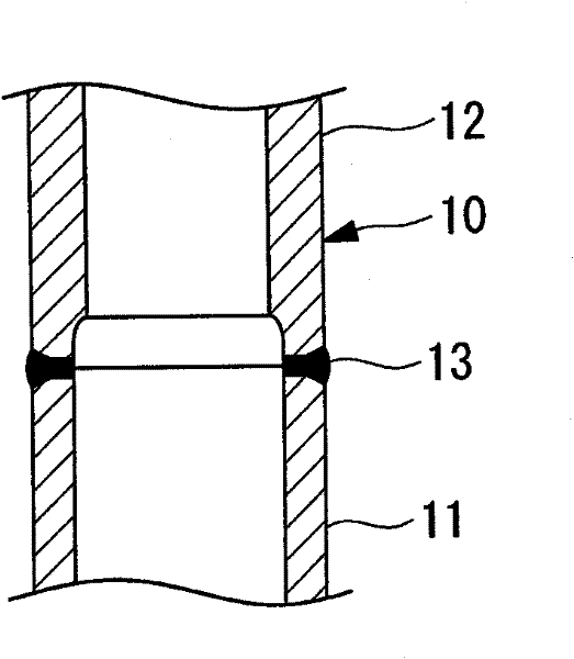
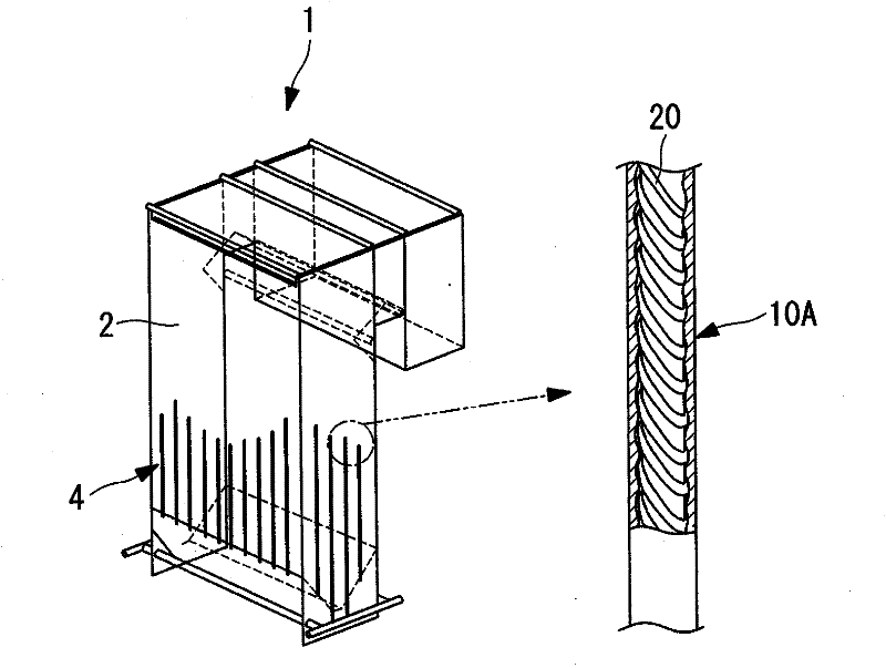
[0022] exist Figure 1 to Figure 3 In the illustrated embodiment, the boiler 1 is constituted as a supercritical once-through boiler with variable pressure, that is, a plurality of boiler evaporating tubes 10 arranged on the wall surface of the furnace 2 form a furnace water wall 4. When the water at 10 flows inside the tube, the water is heated inside the furnace 2 to generate steam. In the illustrated boiler 1 , the horizontal section of the furnace 2 is formed in a rectangular shape, and furnace water walls 4 are formed on four surfaces, front, rear, left, and right.

[0023] figure 1 The shown intermediate header 5 is to make the boiler evaporating tubes 10 protrude temporarily out of the non-heated furnace and gather them above the burner part equipped with the burner 3, and then make it face to the ceiling wall side of the upper part o...


PUM


Abstract

The present invention provides a boiler structure capable of reducing the power of auxiliary devices such as a feed water pump and improving the flow stability and the natural circulating characteristic by so reducing the pressure loss of boiler evaporation tubes as to match a thermal load which changes depending on the distance in a boiler height direction. In the boiler structure, the large number of boiler evaporation tubes disposed on the wall surface of a furnace (2) form a furnace water-cooling screen (4), and the water force-fed to the boiler evaporation tubes is heated in the furnace (2) when flowing through the insides of the tubes, and steam is generated. Multiple types of boiler evaporation tubes connected in the boiler structure have respective wall thicknesses adjusted according to the thermal load of the furnace and respective inner diameters further reduced in the areas where the thermal load of the furnace is larger.

Description

technical field [0001] The present invention relates to a boiler structure including a boiler evaporating tube (furnace water wall) such as a supercritical variable pressure once-through boiler. Background technique [0002] Conventionally, in a supercritical variable pressure once-through boiler, water flows inside a plurality of boiler evaporation tubes arranged on the wall surface of the furnace, and the water is heated by the heat in the furnace to generate steam. This kind of boiler evaporating tube is piped in the up and down direction in the furnace, so that the water pressed in from one side of the boiler evaporating tube flows in one direction without circulation and changes into steam, that is, it is pressed in from the bottom of the furnace. The water changes into steam in the process of flowing upwards towards the upper part of the furnace wall. [0003] For the boiler evaporator tube described above, the inner diameter of the tube is selected appropriately for ...

Claims


Application Information

Patent Timeline
Patent Type & Authority Applications(China)
IPC IPC(8): F22B37/10F22B37/12
CPCF22B37/10F22B37/12
Inventor 堂本和宏菅沼博金卷裕一
Owner MITSUBISHI HEAVY IND LTD
Features
  • Generate Ideas
  • Intellectual Property
  • Life Sciences
  • Materials
  • Tech Scout
  • Unparalleled Data Quality
  • Higher Quality Content
  • 60% Fewer Hallucinations
Learn More