Conveying control method for pneumatic conveying system

A pneumatic conveying system and conveying control technology, applied to conveyors, conveying bulk materials, transportation and packaging, etc., can solve problems such as uncontrollable air volume, difficulty in diagnosis and maintenance of intake valve faults, and large investment

Active Publication Date: 2011-07-27
FUJIAN LONGKING
View PDF4 Cites 23 Cited by
  • Summary
  • Abstract
  • Description
  • Claims
  • Application Information

AI Technical Summary

Problems solved by technology

In this method, due to the large number of intake points and the installation on the overhead pipeline, it is very difficult to diagnose and repair the check valves and intake valves at each intake point, and the gas volume cannot be controlled within a small range, and at the same time, the investment is relatively large.

Method used


Image

  • Conveying control method for pneumatic conveying system
  • Conveying control method for pneumatic conveying system
  • Conveying control method for pneumatic conveying system

Examples


Embodiment Construction

[0019] In order to further understand the present invention, the preferred embodiments of the present invention are described below in conjunction with the examples, but it should be understood that these descriptions are only to further illustrate the features and advantages of the present invention, rather than limiting the claims of the present invention.

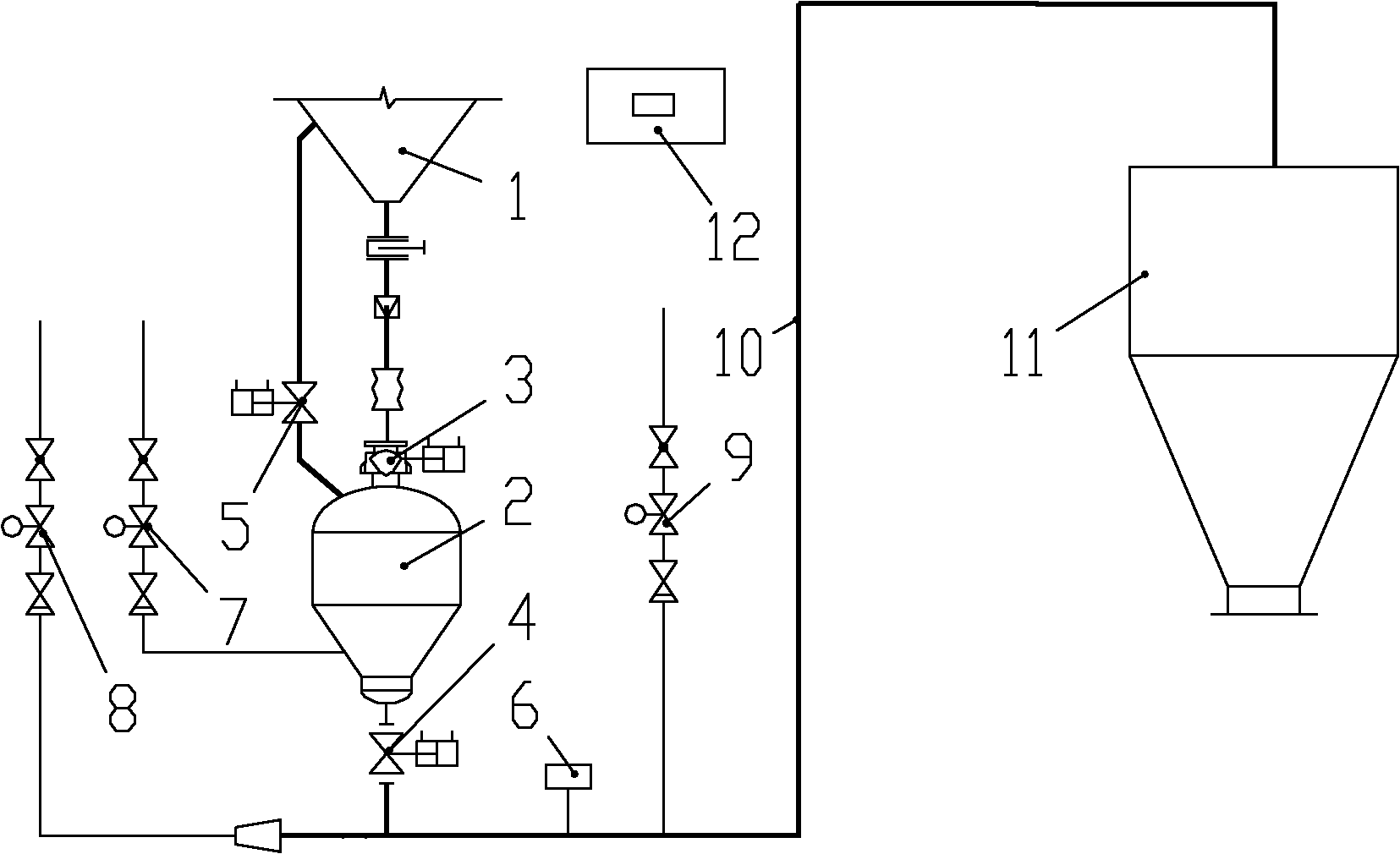
[0020] Please refer to figure 1 , figure 1 It is a schematic diagram of the composition of a conventional pneumatic conveying system. The upper end of the transmitter 2 is connected to the silo 1 through the feed valve 3 and the balance valve 5, and the material enters the transmitter 2 from the silo 1 to be transported; the lower end of the transmitter 2 passes through the discharge valve 4 through the delivery pipeline 10 and the terminal silo 11, the material is transported by the transmitter 2 to the terminal warehouse 11 through the conveying pipeline 10. One end of the air delivery valve 8 is connected to the tai...


PUM


Abstract

The invention provides a conveying control method for a pneumatic conveying system. The conveying control method comprises the following steps of: 1) opening a fluidifying air valve, closing a pipeline air supply valve, comparing conveying real-time pressure with a conveying pressure upper limit, and normally conveying when the conveying real-time pressure is less than or equal to the conveying pressure upper limit, transferring to step 2) when the conveying real-time pressure is more than the conveying pressure upper limit and less than a blockage pressure set value, and transferring to step3) when the conveying real-time pressure is more than or equal to the blockage pressure set value; 2) closing the fluidifying air valve, opening the pipeline air supply valve, and transferring to thestep 1) when the conveying real-time pressure is reduced to a conveying pressure lower limit; and 3) closing all the air valves, transferring to an automatic blockage clearing program, and transferring to the step 1) after the blockage clearing is completed. In the conveying control method, the logic judgment is added on a control system, corresponding air valves are controlled to be opened and closed according to judgment results, the blockage phenomenon is effectively avoided, the time for blockage clearing of the system is shortened, the abrasion and the energy consumption of the system are reduced, and the reliability of the pneumatic conveying system is improved.

Description

technical field [0001] The invention relates to the technical field of conveying materials by gas power, in particular to a conveying control method of a pneumatic conveying system. Background technique [0002] Pneumatic conveying, also known as airflow conveying, uses the energy of airflow to convey granular materials along the direction of airflow in a closed pipeline, which is a specific application of fluidization technology. Pneumatic conveying device is simple in structure and easy to operate. According to the density of particles in the conveying pipeline, pneumatic conveying is divided into dilute phase conveying and dense phase conveying; according to the gas pressure in the pipeline, it is divided into positive pressure and negative pressure. [0003] With the rapid development of the national economy and the country's higher and higher requirements for environmental protection, pneumatic conveying technology has developed rapidly in the past 20 years, especially ...

Claims


Application Information

Patent Timeline
Patent Type & Authority Applications(China)
IPC IPC(8): B65G53/66
Inventor 邱生祥田青张进明潘仁湖江兴涛袁礼
Owner FUJIAN LONGKING
Why Eureka
Try Eureka