Eureka AIR delivers breakthrough ideas for toughest innovation challenges, trusted by R&D personnel around the world.

Rapid drill stem hoisting adapter

A drill pipe, fast technology, applied in the direction of drill pipe, drill pipe, drilling equipment, etc., can solve the problems of not meeting the requirements of on-site construction, high labor intensity of workers, and low work efficiency, and meet the requirements of on-site construction and labor intensity of workers. The effect of low and high work efficiency

Inactive Publication Date: 2011-07-27
DONGYING ZHICHENG TECH
View PDF6 Cites 2 Cited by
  • Summary
  • Abstract
  • Description
  • Claims
  • Application Information

AI Technical Summary

Problems solved by technology

[0002] In the process of oil field drilling, it is necessary to lift the drill pipe on the ground and put the drill pipe in the well on the ground. In this process, a connecting device is needed to connect the drill pipe to the traveling block. At present, a wire plug is used. The male thread of the drill pipe is connected with the female thread of the drill pipe, the plug is hung on the traveling block, and then the drill pipe is hoisted, and the thread is required to be loaded and unloaded when the drill pipe is hoisted with the plug, which is cumbersome and labor-intensive for workers. Low efficiency, long construction time, unable to meet site construction requirements

Method used


Image

  • Rapid drill stem hoisting adapter
  • Rapid drill stem hoisting adapter

Examples


Embodiment Construction

[0008] The embodiments of the present invention will be described below in conjunction with the drawings.

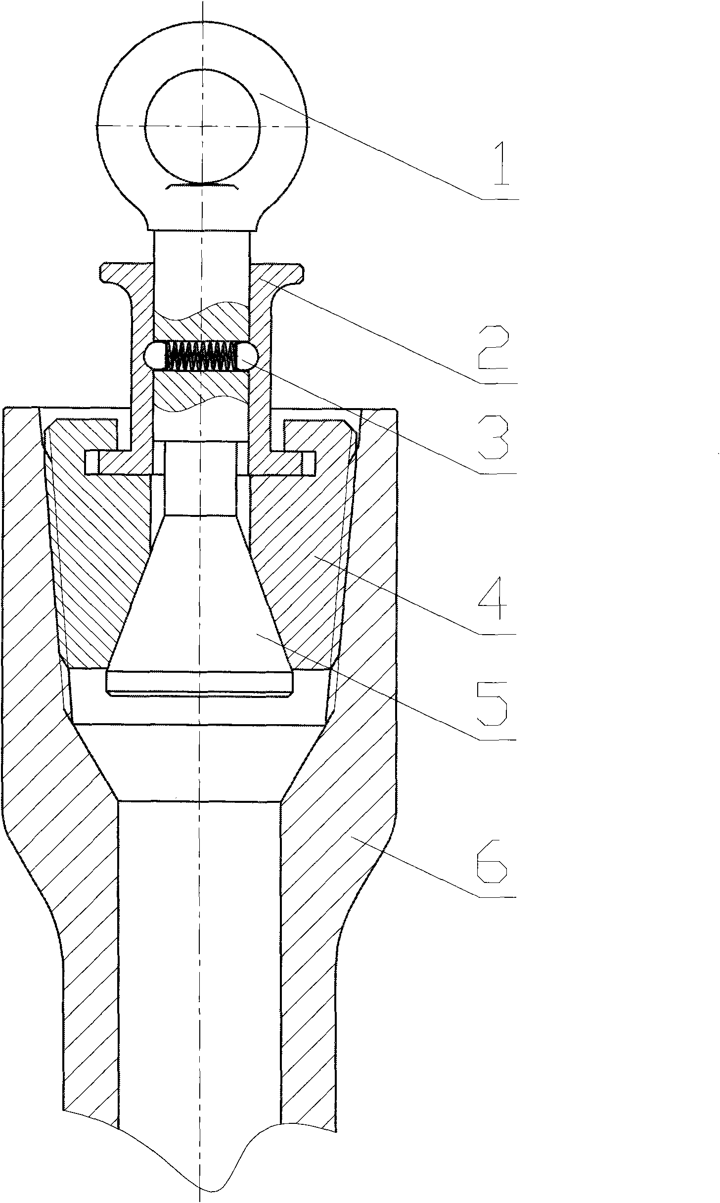
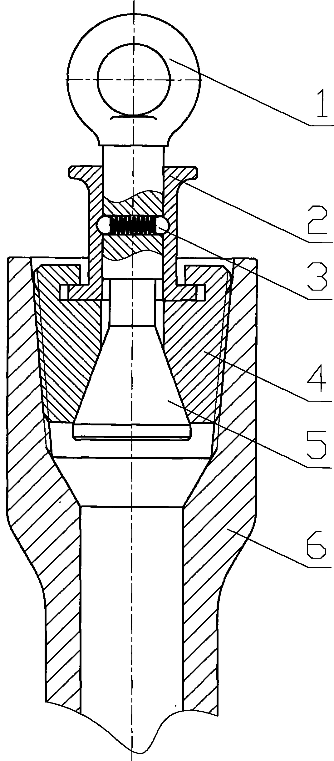
[0009] The embodiment of the present invention includes a lifting ring 1, a linkage sliding sleeve 2, a clamping block 4, a cone 5, and a drill rod 6. The outer wall of the clamping block 4 is an arcuate shape, and the outer wall of the clamping block 4 has a drill pipe thread, and the clamping block 4 The inner wall is conical with a large diameter at the lower end. Several blocks 4 form a cone suspended on the linkage sliding sleeve 2. The ring 1 passes through the linkage sliding sleeve 2. The lower part of the ring 1 is connected to the cone 5, and the upper end of the cone 5 has a small diameter at the lower end. The large diameter is matched with the inner wall of the clamping block 4, and the clamping block 4 is threadedly connected with the drill rod 6. A damping lock 3 is installed between the lifting ring 1 and the linkage sliding sleeve 2, so that the lifting rin...


PUM


Abstract

The invention relates to a rapid drill stem hoisting adapter comprising a drill stem, a lifting ring, a linkage sliding sleeve, fixture blocks, and a cone. The outer walls of the fixture blocks are arc-shaped and provided with drill stem threads, and the inner walls of the fixture walls are tapered. The diameter of the lower end of each fixture block is large. A tapered body formed by a plurality of fixture blocks is suspended on the linkage sliding sleeve, the lifting ring passes through the linkage sliding sleeve, and the lower part of the lifting ring is connected with the tapered body. The tapered body with a small-diameter upper end and a large-diameter lower end is matched with the inner walls of the fixture blocks, the fixture blocks are connected with the drill stem threads, a damping lock is arranged between the lifting ring and the linkage sliding sleeve, the fixture blocks are expanded by lifting the tapered body of the lifting ring upwards so that the threads on the outer walls of the fixture blocks are connected with the threads on the inner wall of the drill stem to press the lifting ring to enable the tapered body to be apart from the fixture blocks, the fixture blocks are retracted, and the threads on the outer walls of the fixture blocks are separated apart from the threads on the inner wall of the drill stem. Therefore, the rapid drill stem hoisting adapter can be rapidly connected with and separated from the fixture blocks, and has advantages of easiness and convenience for hoisting of the drill stem, high operation efficiency, and low labor intensity of workers. The invention can meet requirements of on-site construction, and has obvious economic benefits.

Description

Technical field [0001] The invention is a tool for lifting and lowering drill pipes in petroleum drilling, and is a quick chuck for lifting and lowering drill pipes. Background technique [0002] In the process of oilfield drilling, the drill pipe that is flat on the ground should be lifted and the drill pipe in the well should be placed on the ground. In this process, a connecting device is required to connect the drill pipe with the traveling block. Currently, wire plugging is used. The male thread is connected with the female thread of the drill rod, the plug is suspended on the traveling block, and then the drill rod is hoisted. The use of the plug to hoist the drill rod requires the thread to be loaded and unloaded. The work is complicated and the labor intensity of the workers is high. The efficiency is low, the construction time is long, and the on-site construction requirements cannot be met. Summary of the invention [0003] The purpose of the present invention is to des...

Claims


Application Information

Patent Timeline
Patent Type & Authority Applications(China)
IPC IPC(8): E21B19/06
Inventor 武涛王臣张爱滨钱玉东解传军
Owner DONGYING ZHICHENG TECH
Why Eureka
Eureka Blog
Learn More