Wing span type self-adapting blade structure

A blade structure, self-adaptive technology, applied in the direction of reducing greenhouse gases, climate sustainability, wind turbines, etc., to achieve the effects of novel structure, improved wind power quality, and simple structure

Inactive Publication Date: 2011-07-27
马嗣锋
View PDF8 Cites 12 Cited by
  • Summary
  • Abstract
  • Description
  • Claims
  • Application Information

AI Technical Summary

Problems solved by technology

[0047] In order to solve the technical problem of adjusting the power of the fan of the wind power generation devi

Method used


Image

  • Wing span type self-adapting blade structure
  • Wing span type self-adapting blade structure
  • Wing span type self-adapting blade structure

Examples


Embodiment 1

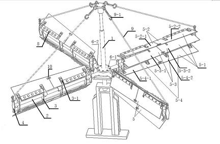
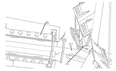
[0092] Embodiment 1: It includes a main shaft 1 , a support rod 2 , two blade supports 3 , two auxiliary supports 4 , two limit rods 7 , two counterweight modules 8 and blade groups 5 . The blade group includes an upper blade 5-2 and a lower blade 5-4. The support rod 2 is connected to the main shaft 1 through a connecting device 6 . An auxiliary bracket 4, two blade brackets 3, and an auxiliary bracket 4 are successively installed on the support rod 2 from the root to the tip. Among the blade bracket 3 and the auxiliary bracket 4, any two brackets are parallel to each other. The limit bar 7 passes through all the blade supports 3 and the auxiliary supports 4 and is parallel to the support bar 2 . One of the limit rods 7 is above the support rod 2 and works with the upper blade 5-2; the other limit rod 7 is below the support rod 2 and cooperates with the lower blade 5-4 to work. The blade 5 - 1 rotates around the installation point 3 - 1 on the blade bracket 3 as the rotati...

Embodiment 2

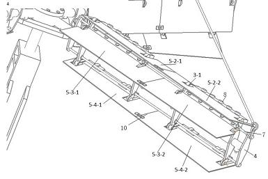
[0101] Embodiment 2: on the basis of embodiment 1, carry out further improvement. Increase the support rod 2 from one to three, the three support rods 2 are on the same plane, and the angle between adjacent support rods 2 is 120 degrees. Four blade supports 3, two auxiliary supports 4, and two limit rods 7 are housed on each support rod. An auxiliary bracket 4, four blade brackets 3, and an auxiliary bracket 4 are installed in sequence from the root of the support rod 2 to the tip. Two limit rods 7 respectively pass through all the above-mentioned blade supports 3 and auxiliary supports 4 , and the two limit rods 7 are respectively located at the upper and lower ends of the support rod 2 . On the mounting point 3-1 of the blade support 3 on the same support rod 2, a piece of upper floor blade 5-2, a piece of middle floor blade 5-3, and a piece of lower floor blade 5-4 are installed. Upper blade 5-2 is divided into 5-2-1 upper blade A and 5-2-2 upper blade B, and 5-2-1 upper ...

Embodiment 3

[0103] Embodiment 3: on the basis of embodiment 2, carry out further improvement. Increase the support rods 2 from three to four, or five, or six. The number and arrangement of the blade support 3 on each support bar 2, the auxiliary support 4, the stop bar 7, the middle blade 5-3, the upper blade 5-2, and the lower blade 5-4 are the same as those in Implementation 2. This technical solution is more suitable for wind farms with lower wind speeds. It can be started with three-level wind, and can even be erected on the top of urban buildings.


PUM


Abstract

The invention relates to a new blade structure of a wind generator, in particular to a wing span type self-adapting blade structure. The wing span type self-adapting blade structure comprises a main shaft, a support rod, a blade support frame, an auxiliary support frame, a blade set, a connecting device, a limiting rod, a counter weight module and a traction device. Under the action of the wind power and the gravity, the wing span type self-adapting blade structure looks like the flapping wings of the birds, the shape of the blade can be automatically adjusted according to the wind speed, and the shape of the blade is converted among the statuses of 'wing spanning-wing fanning-wing spanning-wing fanning...'. The wing span type self-adapting blade structure keeps a larger wind application area under the status of low wind speed, thereby being easy to start up, and reduces the wind resistance of the blade by automatically converting the statuses under the status of high wind speed, thereby avoiding the overhigh rotation speed. The wing span type self-adapting blade structure is exquisite in conception, ingenious in structure, and simple in installation, so that the difficulty of the power control of a wind power fan is solved, and a creative contribution is offered to further reduce the doorsill of the wind generation and the improve the quality of the wind power.

Description

technical field [0001] The invention relates to a blade structure, in particular to a blade structure suitable for a fan of a wind power generation device. Background technique [0002] Facing the threat of depletion of fossil fuels such as coal and oil, renewable energy such as wind energy and solar energy has received great attention around the world. Among them, wind power is one of the renewable energy sources with the most mature technology and the most commercial development prospects in new energy sources. Many countries around the world have long recognized the importance of wind power in adjusting energy structure and alleviating environmental pollution, including Germany, Denmark, Spain, the United States and other developed countries scrambling to develop wind energy. In Asia, India, Japan, and China have also vigorously installed wind turbines in recent years, actively increasing the proportion of wind power generation. According to the 2007 report of the Glo...

Claims


Application Information

Patent Timeline
IPC IPC(8): F03D3/06
CPCY02E10/74
Inventor 马嗣锋
Owner 马嗣锋
Why Eureka
Try Eureka