Light beam correcting projection equipment

A beam and equipment technology, applied in the field of beam correction and projection equipment, can solve problems such as poor uniformity, high illumination requirements, and disordered light path of the detection beam, so as to improve detection precision, reduce illumination requirements, solve diffusion problems and The effect of poor uniformity

Active Publication Date: 2012-07-25
SUZHOU JINGLAI OPTO CO LTD
View PDF0 Cites 0 Cited by
  • Summary
  • Abstract
  • Description
  • Claims
  • Application Information

AI Technical Summary

Problems solved by technology

[0006] The object of the present invention is to solve the problems of disordered light path, poor uniformity and high illuminance requirements of the detection beam in the optical detection system in the known technology, and to provide a beam correction projection device to amplify, homogenize and parallelize the detection beam, greatly reducing the Illumination requirements and at the same time improve the quality of inspection

Method used


Image

  • Light beam correcting projection equipment
  • Light beam correcting projection equipment
  • Light beam correcting projection equipment

Examples


Embodiment Construction

[0043] The light beam correction projection device of the present invention is applied in an optical detection system to correct a detection light beam, and the detection light beam is used to project to an object to be inspected, and the object to be inspected can be a liquid crystal display or a large printed circuit board. A preferred embodiment of the present invention is listed below for illustration.

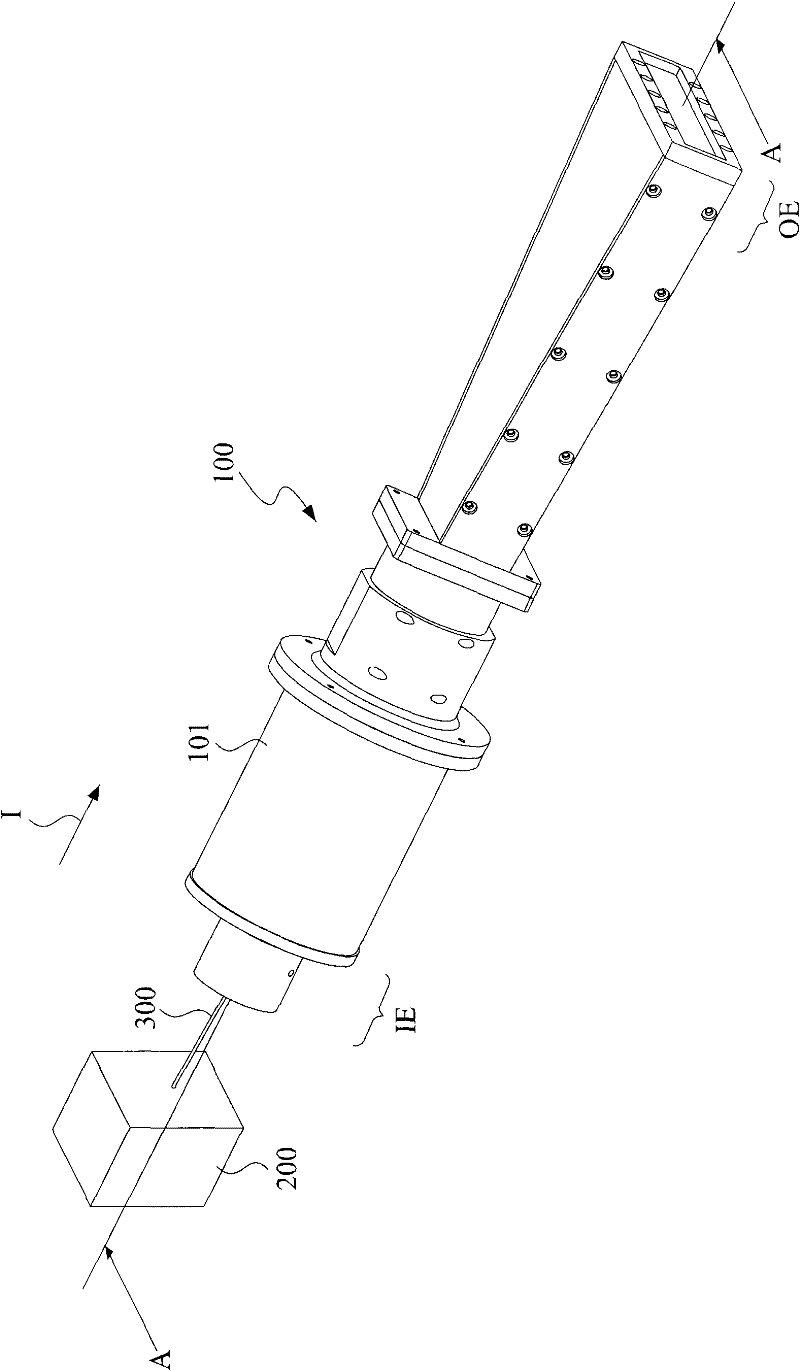
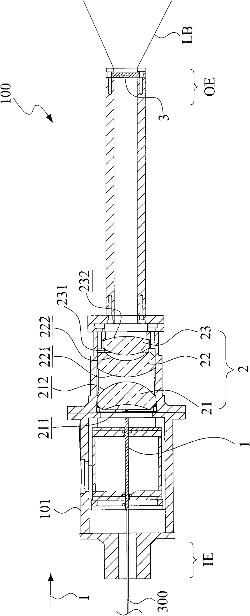
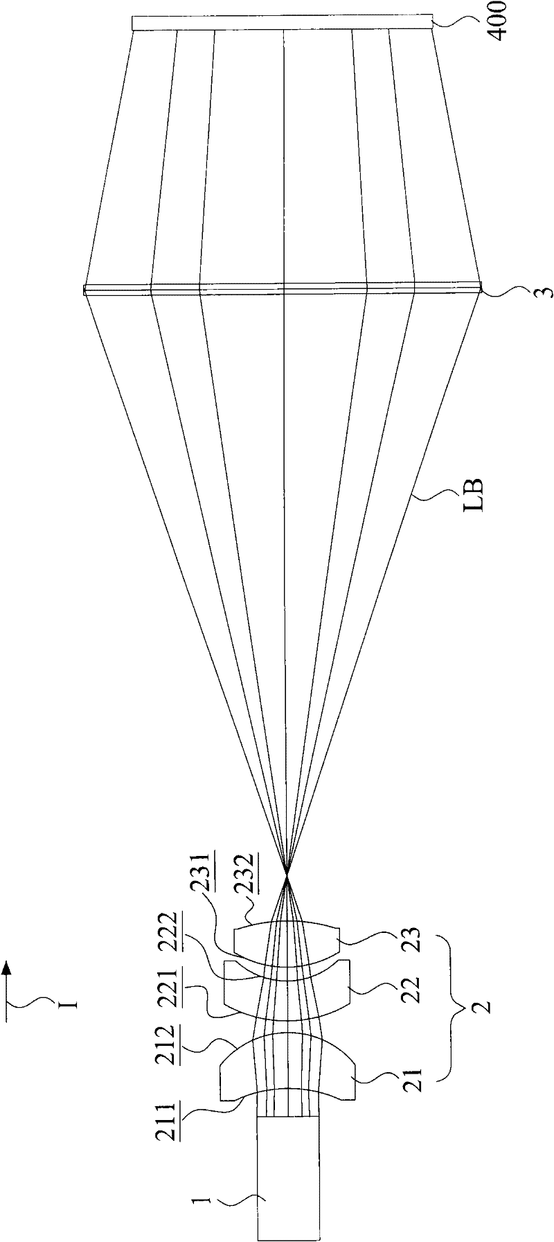
[0044] see figure 1 , which is a three-dimensional appearance view of the beam correction projection device of the present invention. As shown in the figure, the housing 101 of the beam correction projection device 100 has an input end IE and an output end OE, and the input end IE allows a light guide tube 300 that can be an optical fiber to extend into a light box 200. The detection beam LB (not shown) projected by the light source along a projection direction I is introduced into the beam correction projection device 100; the output end OE is projected by the corrected ...


PUM

PropertyMeasurementUnit
refractive indexaaaaaaaaaa

Abstract

The invention relates to light beam correcting projection equipment for correcting a detection light beam projected by a light source along a projection direction, sequentially comprising a light guide slice, a lens group and a Fresnel lens group along the projection direction, wherein the light guide slice amplifies and homogenizes the detection light beam; the lens group has a first effective focal length F1 and includes a concavo-convex lens, a convexo-concave lens and a biconvex lens, and the focal lengths of the concavo-convex lens, the convexo-concave lens and the biconvex lens are respectively f1, f2 and f3; the Fresnel lens group has a second effective focal length F2 and is used for parallelizing the detection light beam, wherein f1 / F1 is more than and equal to 1.5 or less than and equal to 3.5, f1 / f2 is more than and equal to -1.0 or less than and equal to -0.2, f1 / f3 is more than and equal to 2.0 or less than and equal to 3.0, F1 / F2 is more than and equal to 0.1 or less than and equal to 0.4, the convexo-concave lens is 2-8 mm away from the concavo-convex lens, the biconvex lens is 3.1-9.2 mm away from the convexo-concave lens, and the Fresnel lens group is 180-500 mm away from the lens group.

Description

technical field [0001] The present invention relates to a beam correction projection device, in particular to a beam correction projection device used in an optical detection system for correcting a detection beam. Background technique [0002] According to, in the production line of liquid crystal display or large printed circuit board, etc., there is an optical detection step, the detection beam is projected on the substrate, and the image is captured for image processing to inspect the product. [0003] In the optical detection system of the known technology, the light path of the detection beam projected by the light beam projection device is relatively disordered. When detecting a three-dimensional object, it often forms a diffuse and black spot on the detection image, resulting in the problem of detection error. . [0004] Furthermore, in order to inspect defects easily, it is advisable to have a high illuminance of the inspection light beam, so that the known optical...

Claims


Application Information

Patent Timeline
Patent Type & Authority Patents(China)
IPC IPC(8): G02B27/09G01N21/88
Inventor 詹方兴林宜贤
Owner SUZHOU JINGLAI OPTO CO LTD
Why Eureka
Try Eureka