Shift registor circuit

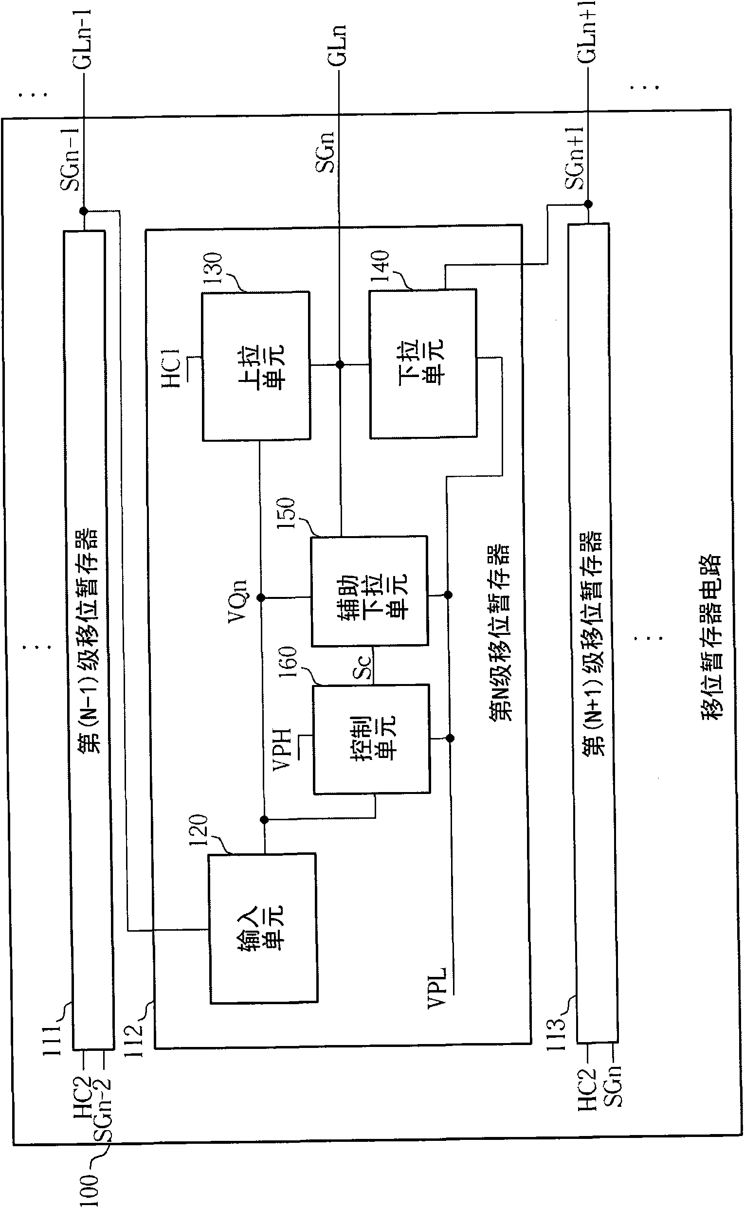
A shift register and circuit technology, applied to instruments, static indicators, etc., can solve the critical voltage offset, shorten the service life of the shift register circuit 100, reduce the pull-down voltage stabilization function of the auxiliary pull-down unit 150, etc. question

Active Publication Date: 2011-07-27
AU OPTRONICS CORP
View PDF5 Cites 16 Cited by
  • Summary
  • Abstract
  • Description
  • Claims
  • Application Information

AI Technical Summary

Problems solved by technology

That is to say, the transistor of the auxiliary pull-down unit 150 works in the forward bias state for a long time, so it is easy to cause the threshold voltage shift phenomenon
If the shift register circuit 100 is integrated on a display panel including a pixel array in order to reduce manufacturing costs, that is, based on the GOA (Gate-driver On Array) architecture, the transistors used in the above-mentioned multi-level shift register It is a thin film transistor (Thin Film Transistor; TFT), so the transistor works in the forward bias state for a long time, which is more likely to cause a serious threshold voltage shift phenomenon, thereby reducing the pull-down voltage regulation function of the auxiliary pull-down unit 150, thereby shortening the shift time. service life of the memory circuit 100

Method used


Image

  • Shift registor circuit
  • Shift registor circuit
  • Shift registor circuit

Examples


Embodiment Construction

[0029] Hereinafter, according to the shift register circuit of the present invention, specific embodiments will be described in detail in conjunction with the accompanying drawings, but the provided embodiments are not intended to limit the scope of the present invention.

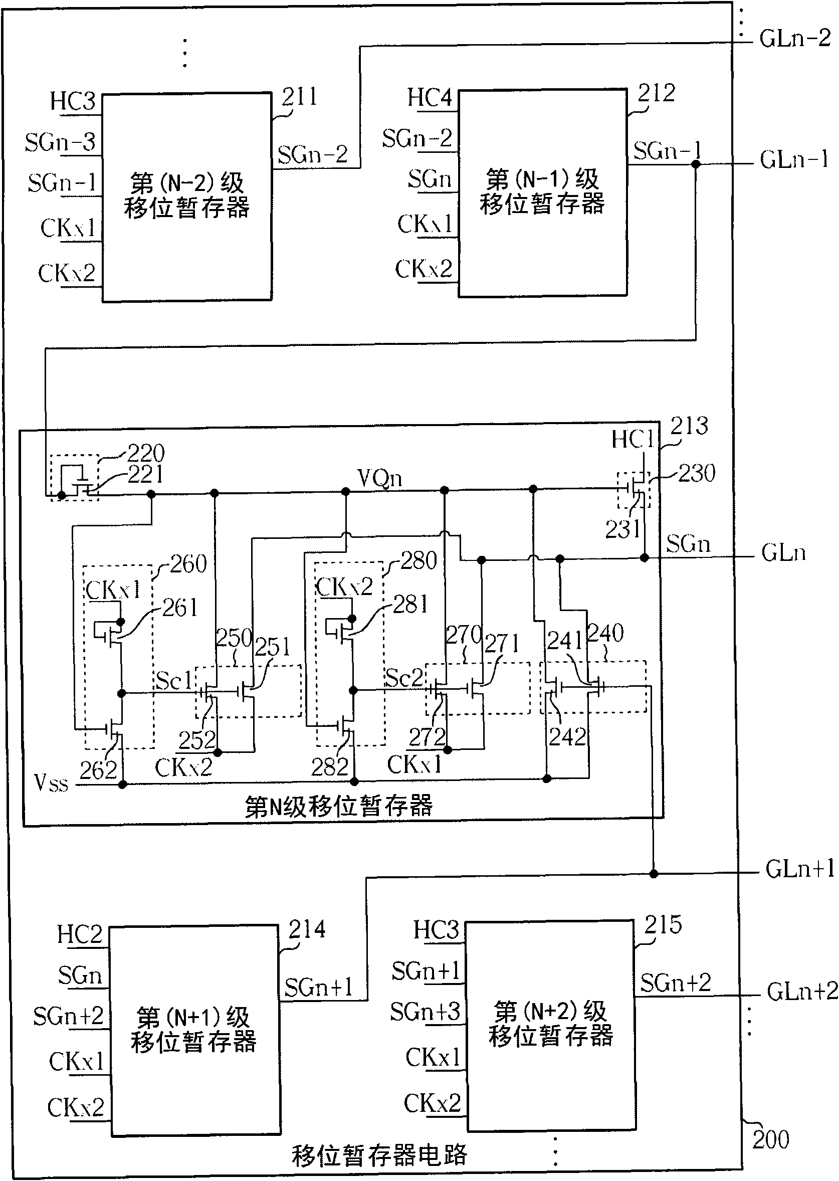
[0030] figure 2 It is a schematic diagram of the shift register circuit according to the first embodiment of the present invention. Such as figure 2 As shown, the shift register circuit 200 includes a multi-stage shift register, wherein only the (N-2)th stage shift register 211, (N-1) stage shift register 212, The N-th stage shift register 213 , the (N+1)-th stage shift register 214 and the (N+2)-th stage shift register 215 are for convenience of description. In the operation of the shift register circuit 200, the Nth stage shift register 213 is used to generate the gate signal SGn-1, the (Nth stage) according to the (N-1) stage shift register 212. +1) The gate signal SGn+1 generated by the stage shift...


PUM


Abstract

A shift registor circuit comprises multi-stage shift registors in order to provide multi-grid signals. Each stage shift registor comprises an input unit, a pull-up unit, a pull-down unit, a control unit and an assistant pull-down unit, wherein, the input unit is used for outputting a driving control voltage based on a first input signal. The pull-up unit is used for pulling up corresponding grid signals on the basis of the driving control voltage and a system sequential pulse. The pull-down unit is applied for pulling down the corresponding grid signals and driving control voltages according to the first input signal. The control unit is used for generating a control signal according to a first auxiliary sequential pulse. The assisting pull-down unit is applied for pulling down corresponding grid signals and driving control voltages on the basis of the control signal and a second auxiliary sequential pulse which has a reversed phase relative to the first auxiliary sequential pulse.

Description

technical field [0001] The present invention relates to a shift register circuit, in particular to a shift register circuit with the function of recovering transistor critical voltage offset. Background technique [0002] A liquid crystal display (Liquid Crystal Display; LCD) is a flat panel display widely used at present, and has the advantages of light and thin appearance, power saving and low radiation. The working principle of the liquid crystal display device is to change the alignment state of the liquid crystal molecules in the liquid crystal layer by changing the voltage difference between the two ends of the liquid crystal layer, thereby changing the light transmittance of the liquid crystal layer, and then cooperate with the light source provided by the backlight module to display images. Generally speaking, a liquid crystal display device includes a multi-pixel unit, a source driver and a shift register circuit. The source driver is used to provide multiple data ...

Claims


Application Information

Patent Timeline
Patent Type & Authority Applications(China)
IPC IPC(8): G09G3/20G09G3/36
Inventor 林志隆涂俊达吴佳恩陈勇志
Owner AU OPTRONICS CORP
Why Eureka
Try Eureka