Boost double-voltage power factor correction circuit utilizing reverse blocking IGBT

A power factor correction and circuit technology, which is applied to output power conversion devices, electrical components, high-efficiency power electronic conversion, etc., to achieve the effects of simple topology, good electromagnetic compatibility, and improved system efficiency

Inactive Publication Date: 2011-07-27
ZHEJIANG UNIV
View PDF0 Cites 9 Cited by
  • Summary
  • Abstract
  • Description
  • Claims
  • Application Information

AI Technical Summary

Problems solved by technology

It is worth noting that although this circuit does not require an uncontrolled rectifier bridge, it still requires two input rectifier diodes

Method used


Image

  • Boost double-voltage power factor correction circuit utilizing reverse blocking IGBT
  • Boost double-voltage power factor correction circuit utilizing reverse blocking IGBT
  • Boost double-voltage power factor correction circuit utilizing reverse blocking IGBT

Examples


Embodiment Construction

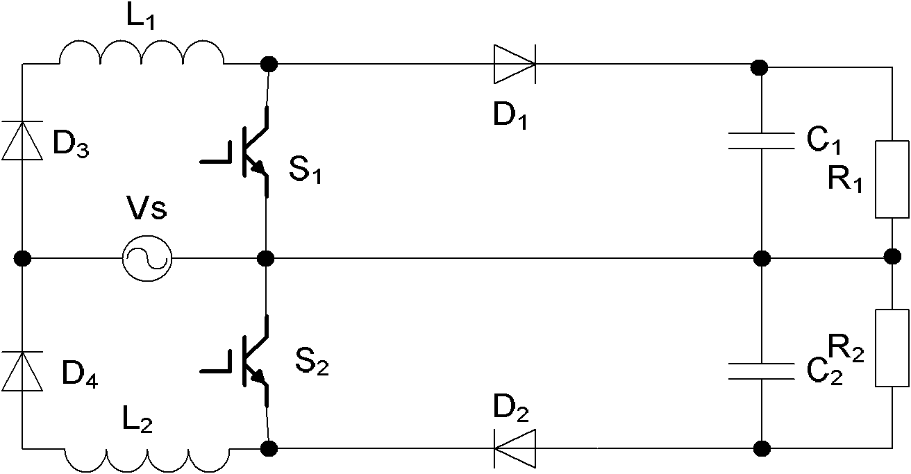
[0022] Such as Figure 4 As shown, two Boost inductors (the first input inductor L 1 , the second input inductance L 2 ), both with the input supply V s connected at the same end;

[0023] The first switch tube S 1 , the second switch tube S 2 Using a reverse resistance IGBT with reverse voltage blocking capability, the first input inductance L 1 , the second input inductance L 2 The other end is connected to the input supply V s The other end of the inductor is not directly connected to form a charging circuit respectively;

[0024] The first output rectifier diode D 1 , the second output rectifier diode D 2 , respectively, the first input inductance L 1 , the second input inductance L 2 connected to the first output filter capacitor C 1 , the second output filter capacitor C 2 ;The first output filter capacitor C 1 , the second output filter capacitor C 2 can be respectively connected to the first load R 1 , the second load R 2 .

[0025] Such as Figure 5...


PUM


Abstract

The invention discloses a Boost double-voltage power factor correction circuit utilizing a reverse blocking insulated gate bipolar transistor (IGBT). The circuit comprises two input inductors, two switching tubes, two output rectifier diodes, and two output filter capacitors, wherein both of the two input inductors are connected with the same end of an input power supply; the two switching tubes respectively connect the other end of each of the two input inductors to the other end of the input power supply not directly connected with the inductors so as to form a charging loop respectively; the two output rectifier diodes connect the two input inductors to the two output filter capacitors respectively; and the output filter capacitors can be connected with a load respectively. Due to the adoption of the reverse blocking IGBT, an input rectifier diode can be saved; on one hand, the total amount of the circuit devices is reduced so as to save the cost; and on the other hand, the number of conducting semiconductor devices on a current path is reduced so as to reduce conduction loss and contribute to improving the efficiency of an overall machine. In addition, the circuit has high electro magnetic compatibility (EMC) by utilizing two input inductors compared with using a single inductor.

Description

technical field [0001] The invention relates to a power factor correction circuit, in particular to a Boost power factor correction (PFC) circuit using an anti-resistance IGBT as a switch tube and using two input inductors. Background technique [0002] At present, single-phase power factor correction circuits have been widely researched and used, the most typical of which is figure 1 The Boost power factor correction circuit shown. For some applications that require dual output voltages, such as UPS systems with a half-bridge structure in the inverter part, because it is difficult to obtain a relatively stable midpoint potential, this typical Boost power factor correction circuit is not very suitable. The flat Boost power factor correction circuit can just meet this kind of application. [0003] Such as figure 2 Shown in is the paper "Single-phase Three-Level Boost Power Factor Correction Converter (in: Proceedings of Tenth Annual Applied Power Electronics Conference an...

Claims


Application Information

Patent Timeline
Patent Type & Authority Applications(China)
IPC IPC(8): H02M1/42
CPCY02B70/126Y02B70/10Y02P80/10
Inventor 马皓阳彩
Owner ZHEJIANG UNIV
Why Eureka
Try Eureka