Method for producing a hot-forming tool and hot-forming tool with wear protection

A technology of thermoforming and thermoforming, which is applied in the field of manufacturing thermoforming molds for thermoforming processing of plate components, which can solve the problems that the wear resistance of materials cannot meet the requirements, and achieve the effect of economical matrix cutting processing

A technology of thermoforming and thermoforming, which is applied in the field of manufacturing thermoforming molds for thermoforming processing of plate components, which can solve the problems that the wear resistance of materials cannot meet the requirements, and achieve the effect of economical matrix cutting processing

CN102139326BActive Publication Date: 2014-09-10BENTELER AUTOMOBILTECHNIK GMBH

Image

  • Method for producing a hot-forming tool and hot-forming tool with wear protection
  • Method for producing a hot-forming tool and hot-forming tool with wear protection
  • Method for producing a hot-forming tool and hot-forming tool with wear protection

Examples


Embodiment Construction

[0037] In the figures, the same reference numerals are used for identical or similar parts / components, wherein corresponding or equivalent advantages can be achieved even if the description is not repeated for the sake of simplification.

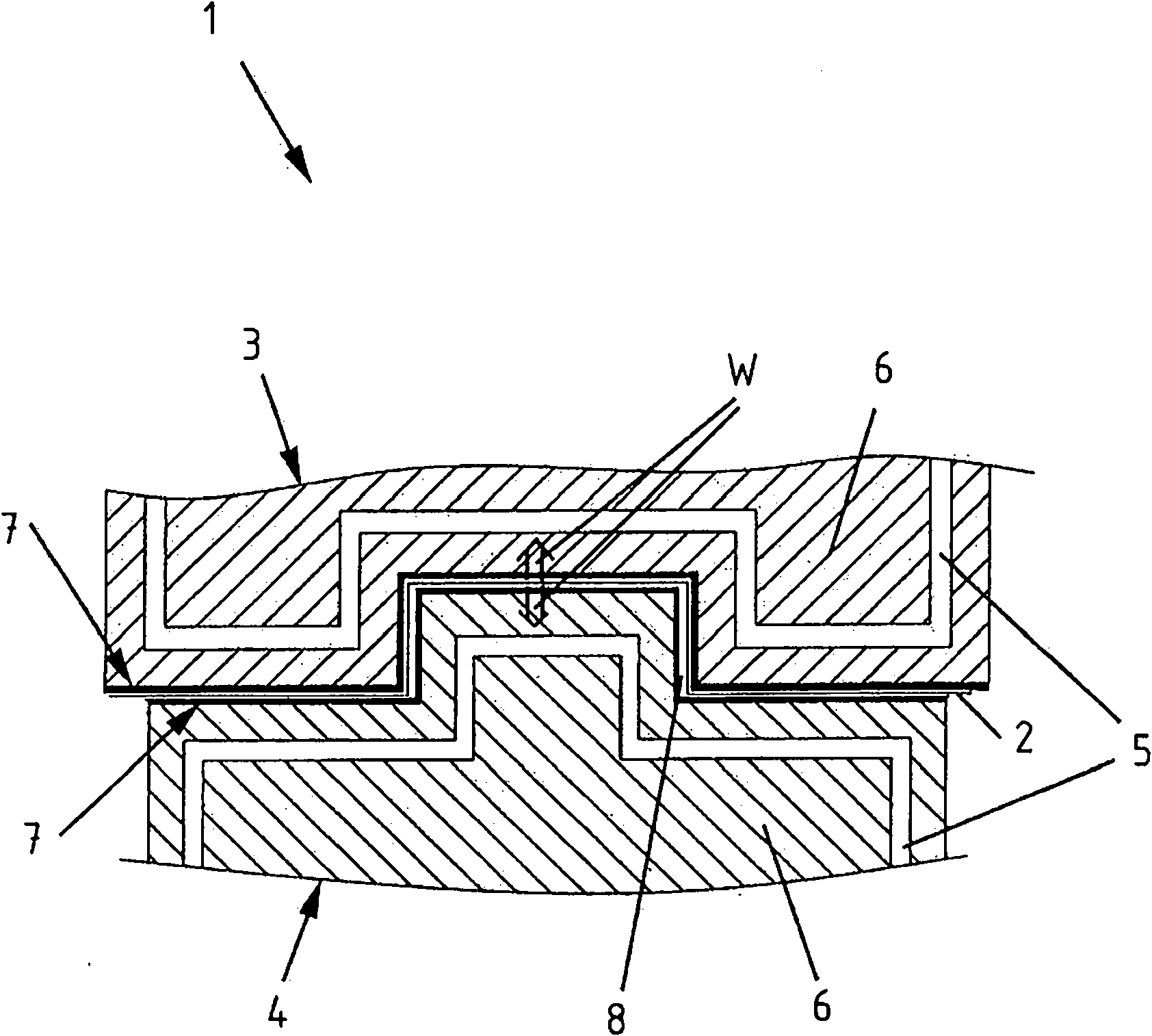
[0038] figure 1 A cross-sectional view of a thermoforming die 1 according to the invention is shown. The thermoforming tool 1 is shown in the closed state. The deformed plate member 2 is located between the upper die 3 and the lower die 4 . The upper mold 3 and the lower mold 4 here comprise a base body 6 with cooling channels 5 . A heat removal fluid flows through these cooling channels 5 . A mold lining 7 is arranged on the base body 6 on the side of the sheet metal component. The mold lining 7 protects the base body 6 against high wear and forms the boundary of the mold cavity 8 . The heat transfer W of the sheet metal component 2 produced due to the heating of the sheet metal component 2 via the mold lining 7 to the base body 6 . N...


PUM

PropertyMeasurementUnit
thicknessaaaaaaaaaa

Abstract

The tool (1) has an upper tool (3) and a lower tool (4) with a base body (6) made of non-ferrous metal or aluminum alloy, and a molded bellow (7) arranged at the base body, where the molded bellow limits a molded cavity (8) of the tool. The molded bellow is formed as a detachable wear protective plate that is connected with the base body by soldering or adhesive. The base body has cooling channels (5) made of copper, stainless steel, aluminum or steel, and the molded bellow has a wear protective coating made of steel. : Independent claims are also included for the following: (1) a method for manufacturing a thermoforming tool (2) a method for separating a wear protective plate from a base body. USE : Thermoforming tool for thermoforming and press hardening sheet components i.e. body structural parts, of a motor vehicle. ADVANTAGE : The molded bellow is arranged at the base body and formed as the detachable wear protective plate that is connected with the base body by soldering or adhesive, thus protecting the base body against wear, and exchanging the protective plate without damaging the base body, and hence reducing manufacturing and maintenance cost of the tool while increasing productivity of the tool. DESCRIPTION OF DRAWINGS : The drawing shows a cross-sectional view of a thermoforming tool. 1 : Thermoforming tool 3 : Upper tool 4 : Lower tool 5 : Cooling channels 6 : Base body 7 : Molded bellow 8 : Molded cavity.

Description

technical field [0001] The invention relates to a thermoforming mold for thermal processing of sheet metal components, comprising an upper mold and a lower mold, which have a base body made of non-ferrous metal which is easy to machine and a mold liner arranged on the base body, said base body having The cooling channel, the mold liner forms the boundary of the mold cavity of the thermoforming mold. [0002] The invention also relates to a method of manufacturing a thermoforming die for the thermoforming of sheet metal components, the thermoforming die comprising an upper die and a lower die having a base body composed of a non-ferrous metal easily machined and arranged on the base body A mold liner, the base body having cooling channels, the mold liner delimits a mold cavity of a thermoforming mold. [0003] The invention also relates to a method for separating a mold liner from a base body of a thermoforming mold. Background technique [0004] Hot forming dies are known ...

Claims


Application Information

Patent Timeline
10 Sep 2014
Publication
CN102139326B
IPC
B21D37/10; B21D37/16
CPC
B21D37/20; B21D37/16
Inventors
J·德尔; M·佩尔曼