High-tension steel grating
A high-tensile, steel grid technology, applied in the field of grid-like grids, can solve the problems of no specific high-tensile steel, thin plate thickness, etc., to eliminate the reduction of plane retention strength, eliminate deformation problems, and avoid shedding effect
- Summary
- Abstract
- Description
- Claims
- Application Information
AI Technical Summary
Problems solved by technology
Method used
Image
Examples
Embodiment 1
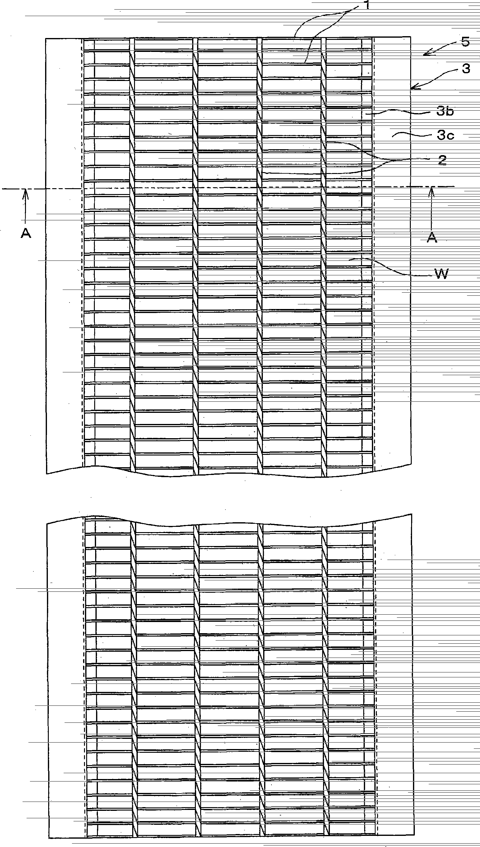
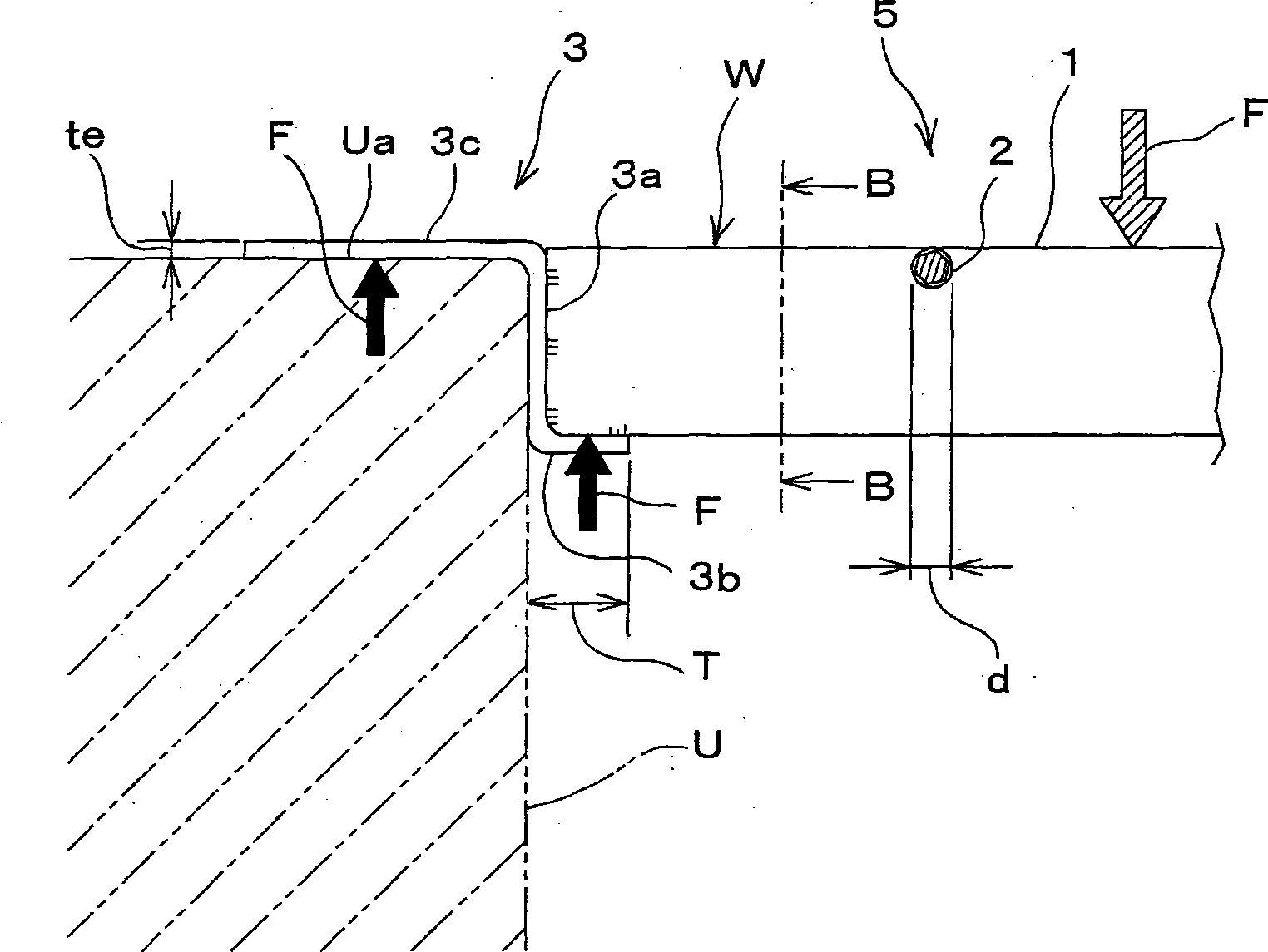
[0044] Fig. 1 shows an embodiment of the high-tensile steel grating of the present invention, (a) is its front view (plan view), and (b) is an AA sectional view of (a). Fig. 2(a) is a sectional view of main parts showing the state of use of the high-tensile steel grating of Fig. 1 , and (b) is a BB sectional view of (a).
[0045] As shown in Figure 2(a), the high-tensile steel grid 5 is a so-called folded grid, which is used for the cover of the U-shaped ditch U of the road. In the state where the cross profile 2 does not protrude from the upper end surface of the load-bearing profile 1, the upper end side of the load-bearing profile 1 is connected by the cross profile 2 by resistance butt welding to form a lattice window W, and the ends of the load-bearing profile 1 are respectively connected by the end profile 3. both ends.
[0046] The high-tensile steel grating 5 includes the above-mentioned basic structure, especially the high-tensile steel plate is used as the raw mater...
Embodiment 2
[0065] Fig. 3 shows other embodiments of the high-tensile steel grating of the present invention, (a) is an external perspective view of its use state, (b) is a sectional view of its main part, and (c) is the C arrow direction of (b) view.
[0066] In FIG. 3( a ), the high-tensile steel grid 5A is shown as a cover of the road side ditch UA, and is installed on the grid receiving portion Ub. However, it can also be used for floors of other clean rooms or multi-storey car parks, etc., or for treads of steps.
[0067] Compared with the high-tensile steel grating 5 shown in Figures 1 and 2, its composition is different in that: the end profile 3A is supported by the grid receiving part Ub of the side ditch UA, and does not bear the load applied to the load-bearing profile 1, which is A flat profile made of general structural steel with a generally rectangular cross-section.
[0068] That is, the high-tensile steel grating 5A is characterized in that in the grating without hems, ...
Embodiment 3
[0073] Fig. 4 shows other embodiments of the high tensile steel grating of the present invention, (a) is its front view, (b) is its plan view, (c) is the DD sectional view of (b), (d) is its use The front view of the state, (e) is the side view of (d).
[0074] As shown in Figure 2(d) and (e), the high-tensile steel grid 5B is characterized in that it is used as a cover grid for the opening VA of the circular side groove V, and the load-bearing profiles except the two outer parts 1B The raw material of 1A and cross section 2A is high tensile steel. In addition, reference numeral 3B is an end profile.
[0075] That is, compared with the high-tensile grid 5 of FIG. 1, the difference lies in the aspect of the elongated opening WA for the circular side groove W in the longitudinally aligned state, and not only the load-bearing profile 1A, but also the cross profile 2A It is also a high-tensile steel with a rectangular cross-section, and a groove for inserting the cross section 2...
PUM
 Abstract
Description
Claims
Application Information
 - R&D
- Intellectual Property
- Life Sciences
- Materials
- Tech Scout
- Unparalleled Data Quality
- Higher Quality Content
- 60% Fewer Hallucinations
Browse by: Latest US Patents, China's latest patents, Technical Efficacy Thesaurus, Application Domain, Technology Topic, Popular Technical Reports.
© 2025 PatSnap. All rights reserved.Legal|Privacy policy|Modern Slavery Act Transparency Statement|Sitemap|About US| Contact US: help@patsnap.com


