Image processing box

A technology of image processing and development unit, which is applied in electrography, optics, instruments, etc., can solve the problems affecting the accuracy of state recognition information of image processing boxes, and achieve high accuracy and precise detection time

Active Publication Date: 2011-08-03
NINESTAR CORP
View PDF4 Cites 0 Cited by
  • Summary
  • Abstract
  • Description
  • Claims
  • Application Information

AI Technical Summary

Problems solved by technology

However, due to the combined error caused by the aging of the torsion spring and the resistance of the toner, the time value for the light transmission window on the code wheel to pass through the code detection unit has uncertainty and changes within the error range, which will affect the image processing box. Accuracy of state identifying information

Method used


Image

  • Image processing box
  • Image processing box
  • Image processing box

Examples


Embodiment 1

[0028] Embodiment 1: Image processing box using cam slider device

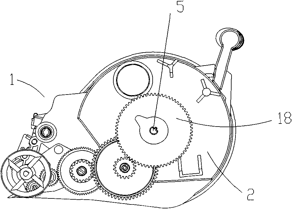
[0029] figure 1 The shown developing unit 1 mainly includes a stirring frame shaft 5 supported on both side walls of the developing unit 1 , a powder bin 2 containing toner inside, and an assembly 18 installed outside the side wall of the developing unit 1 .

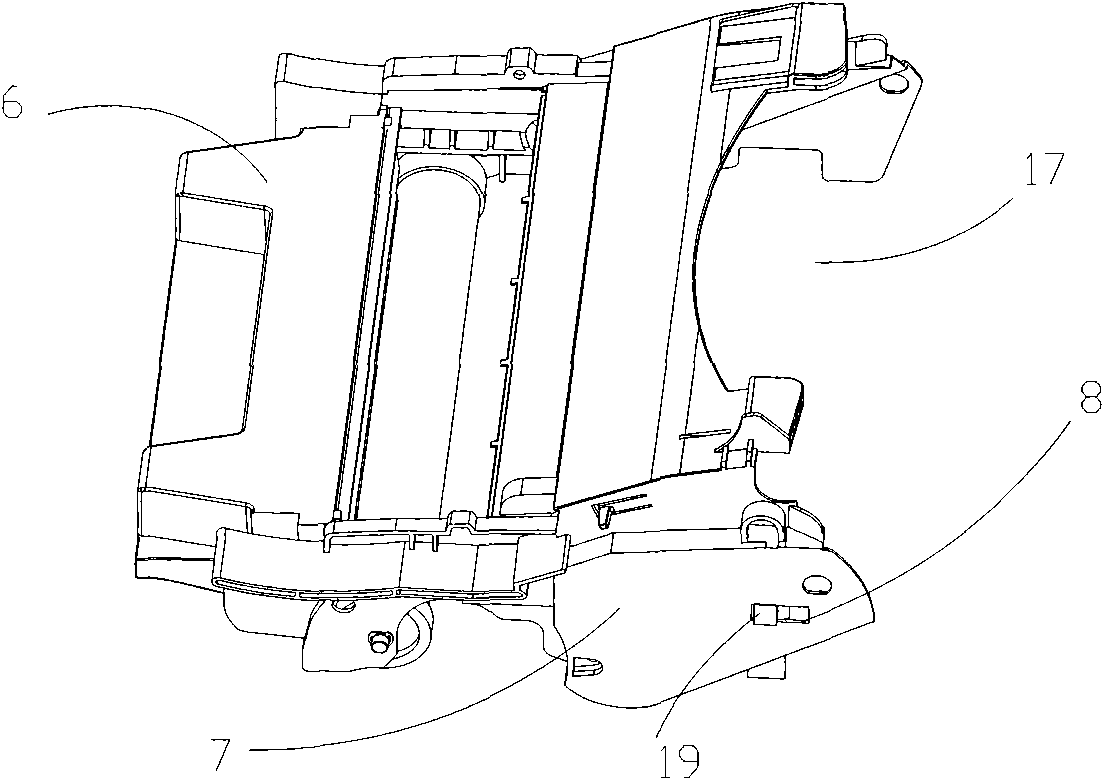
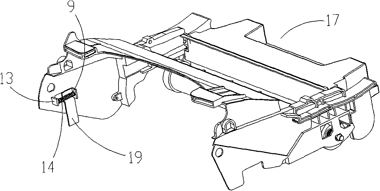
[0030] figure 2 , image 3 The photosensitive drum cartridge 17 shown mainly includes a waste toner bin 6, a slider shielding piece assembly 19, a spring 9, and a side wall 7 on which the sliding block shielding piece assembly is assembled, wherein the wall 7 includes a rectangular window shape. The slider track 8 has a support block 13 on the inner wall surface of the wall 7 perpendicular to the inner wall surface, and a cylindrical protrusion 14 is provided on one side of the 13 for supporting the spring 9 . From two perspective views in different directions, it can be seen that the assembled sliding block shielding sheet assembly 19 is installed o...

Embodiment 2

[0038] Embodiment 2: Image processing box using rack and pinion device

[0039] Figure 11 , Figure 12 As shown, the gear assembly 23 is integrally formed, and includes a half-key hole 20 for matching the shaft of the stirring frame in the developing unit, a driving gear 21 for driving the shaft of the stirring frame to rotate, and a fan-shaped gear 22, wherein the fan-shaped The gear angle β determines the time when the shutter 26 in the rack-slider assembly 27 is opened at the code reader position.

[0040] The slider assembly 27 is integrally formed, and includes an opaque shielding piece 26, a cylindrical protrusion 25 perpendicular to the plane of the shielding piece 26 for connecting the spring (not shown in the figure), a sliding block 40, and a sliding block 40. There is a flange above and below for positioning the slider 40 in the track to prevent it from slipping out of the assembly track. The slider track and the spring connecting support member matched with the r...

Embodiment 3

[0041] Embodiment 3: Image processing box using crank slider device

[0042] Figure 13 The shown crank assembly 30 is integrally formed, and includes a half-key hole 28 for fitting the shaft of the agitator in the developing unit, a drive gear 39 for driving the shaft of the agitator to rotate, and a drive gear 39 on the outer surface of the drive gear 39. Extend the shaft 29.

[0043] Figure 14 The illustrated slider assembly 37 includes an opaque shutter 36 , a projecting axis 35 perpendicular to the plane of the shutter, and a slider 38 . Wherein, the upper and lower sides of the sliding block 38 are respectively provided with a flange, which is used for the positioning of the sliding block in the track, so as to prevent it from slipping out of the assembling track. The slider track matched with the slider assembly 37 is also located on one side wall of the photosensitive drum cartridge housing, which will not be described here.

[0044] Figure 15 The shown connecti...


PUM


Abstract

The invention relates to an image processing box in an electronic photographic imager. The image processing box comprises a development unit and a photosensitive drum box, wherein the photosensitive drum box is detachably assembled with the development unit; the image processing box further comprises a coding device for transmitting state identification information to the electronic photographic imager, which the coding device consists of a plane mechanism; and linear reciprocating motion of a signal shading sheet in the coding device is realized by the rotating action of a driving gear. By adopting the technical scheme, the plane mechanism device is adopted in the coding device, and the motion loci of the composition members of the plane mechanism device have high accuracy, so that the detection time that the non-transparent shading sheet passing through a code reader in the set time is more accurate; and compared with a coding wheel device driven by a torsion spring coupling device,the image processing box can be accurately identified all the time and effectively operated is ensured more accurately and effectively.

Description

technical field [0001] The present invention relates to an image processing cartridge in an electrophotographic imager. Background technique [0002] The electrophotographic imager converts text and graphic information to generate a laser beam, and then scans the photosensitive drum along the axis of the photosensitive drum at a constant speed through a series of optical systems, thereby forming an electrostatic latent image corresponding to the input information on the photosensitive drum. After a series of actions, it is transferred to the electrostatic latent image part to form a visible image, and the visible image of the developer formed on the photosensitive drum is finally transferred and fixed on the recording medium. [0003] After many uses, electrophotographic imagers require various maintenance work, such as replacing the photosensitive drum, replenishing the developer, adjusting the charging element, cleaning the waste toner container, and so on. Therefore, ele...

Claims


Application Information

Patent Timeline
Patent Type & Authority Applications(China)
IPC IPC(8): G03G21/18
Inventor 吴连俊陈维盛彭庆菲余玲玲
Owner NINESTAR CORP
Why Eureka
Try Eureka