
Aerator

A kind of technology of aerator and output shaft, which is applied in the direction of water aeration, sustainable biological treatment, water/sludge/sewage treatment, etc. It can solve the problems that the oxygenation capacity and effect cannot be further improved, and achieve structural design Reasonable, save energy, improve the effect of oxygenation capacity

Inactive Publication Date: 2011-08-10
广东顺德凯雷机械有限公司
View PDF7 Cites 2 Cited by
  • Summary
  • Abstract
  • Description
  • Claims
  • Application Information

AI Technical Summary

Problems solved by technology

[0002] The most commonly used aerators with better aeration effect in the aquaculture industry include impeller aerators, waterwheel aerators, jet aerators, etc., but these aerators are only equipped with one type of impeller. Therefore, the method and function of oxygenation are limited to one type, and the oxygenation capacity and effect cannot be further improved.

Method used


Image

  • Aerator
  • Aerator
  • Aerator

Examples


Embodiment

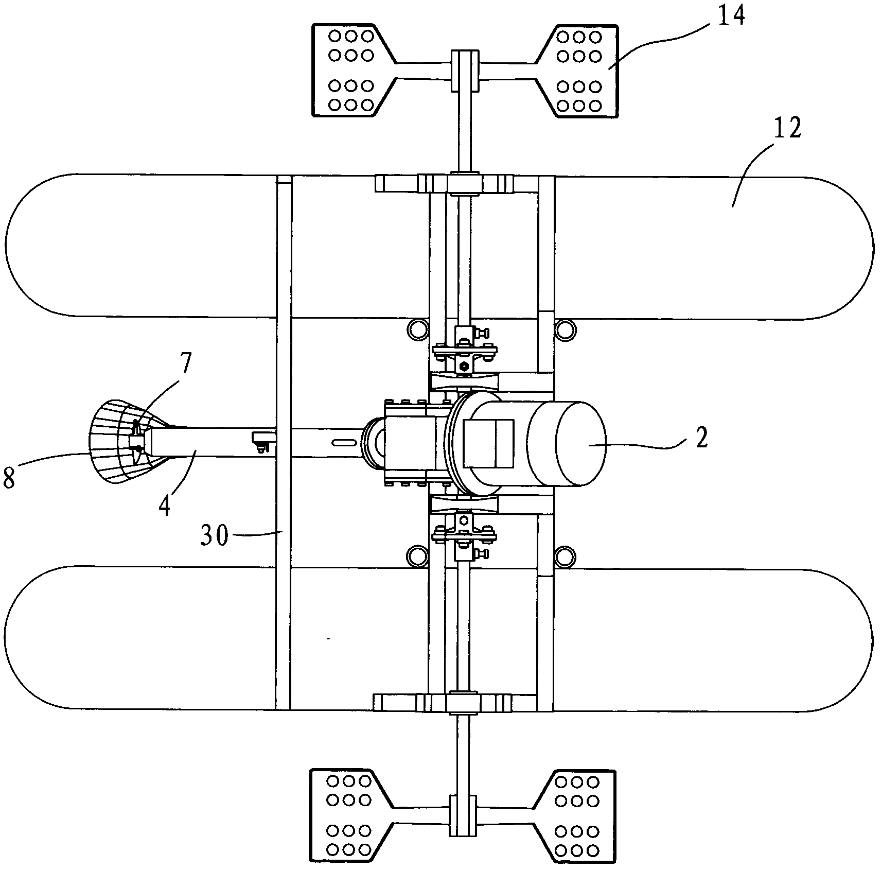
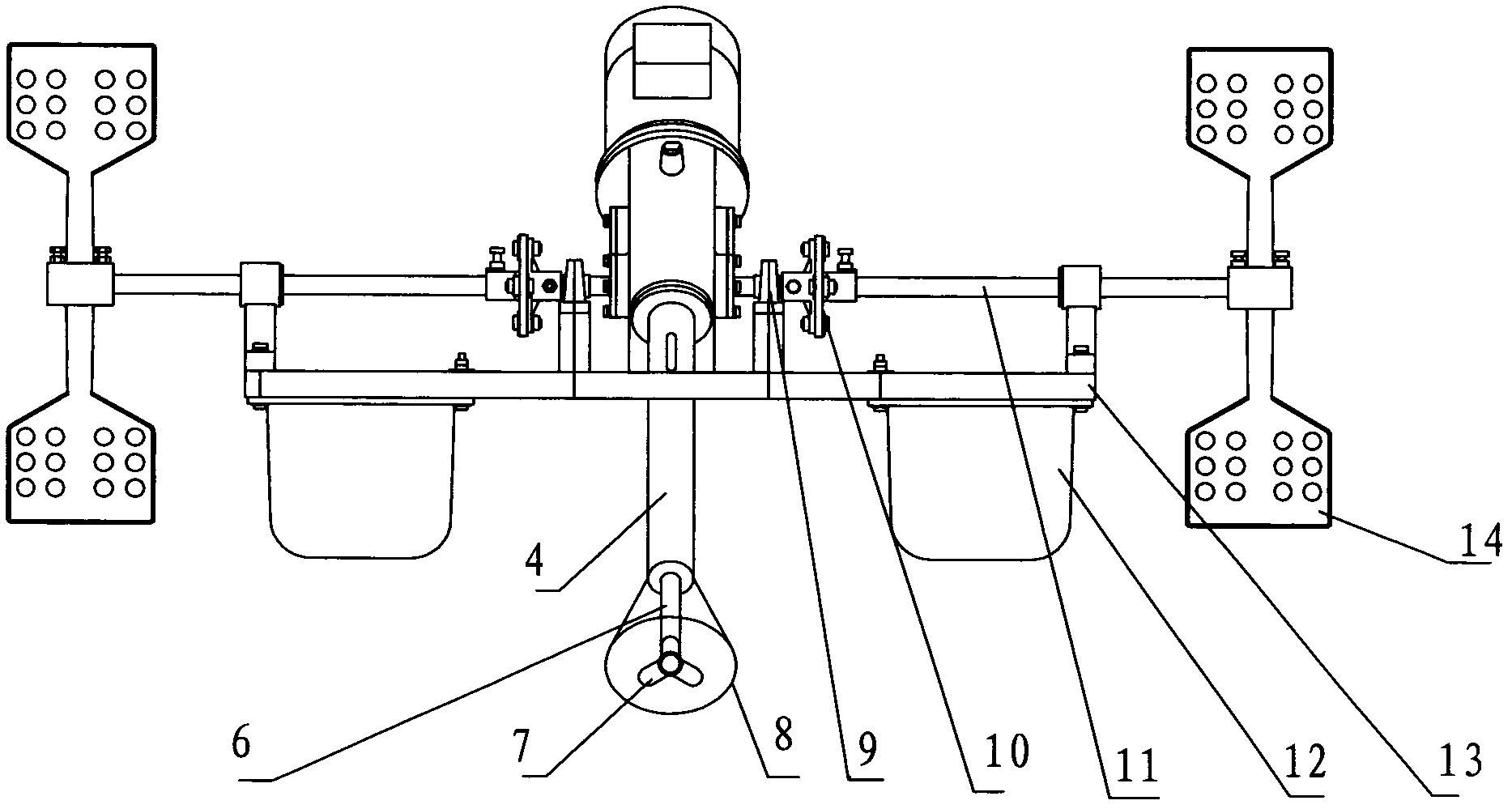
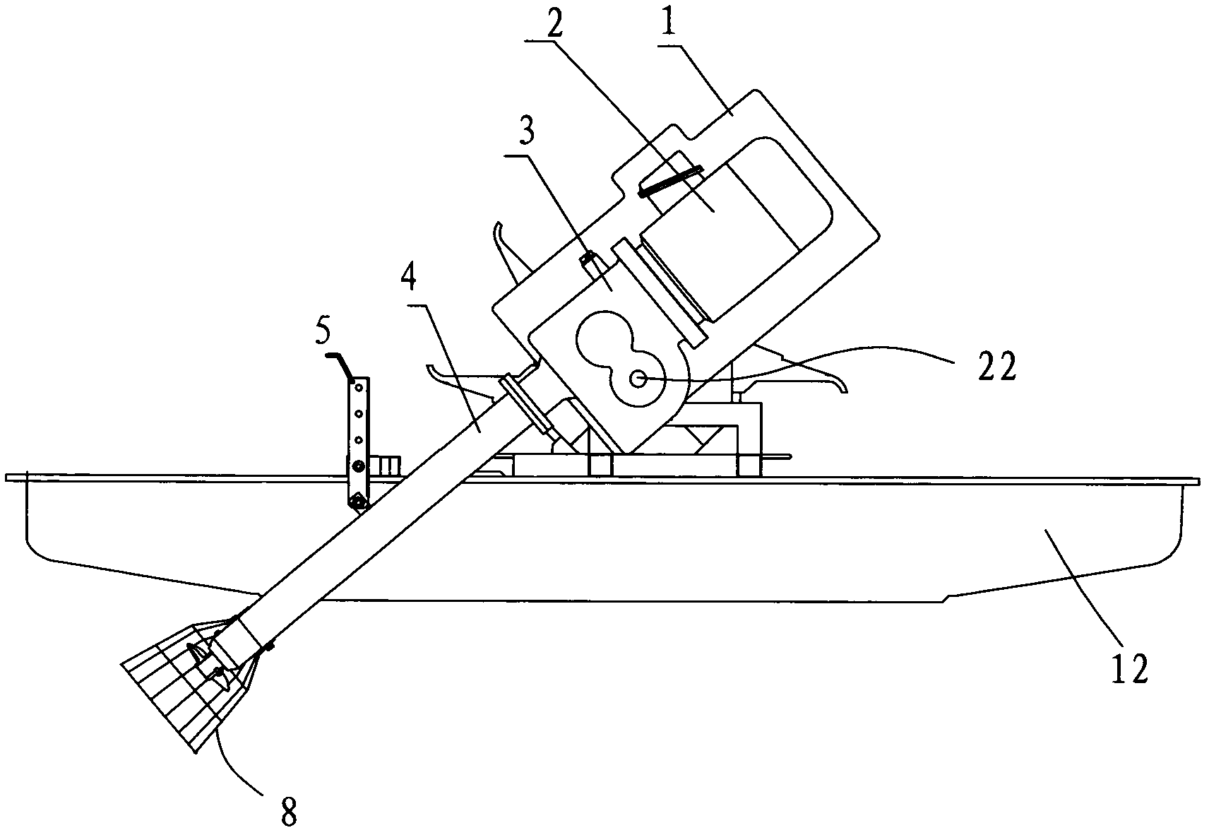
[0018] Example, combined with Figure 1 to Figure 6 . A water wheel jet type aerator, including a waterproof cover 1, a motor 2, a reducer 3, a support tube 4, an adjustment rod 5, a transmission shaft tube 6, a propeller impeller 7, a protective cover 8, a bearing seat 9, and a shaft coupling Joint 10, transmission shaft 11, floating body 12, frame 13, waterwheel impeller 14. The frame 13 supports the speed reducer 3 above the floating body 12 .

[0019] The motor 2 is output and rotated by the horizontal output shaft 22 and the vertical output shaft 19 after being shifted by the reducer 3 . Both ends of the horizontal output shaft 22 protrude from the reducer 3 to support the reducer 3 on the bearing housing 9; the vertical output shaft 19 can swing within a certain range around the horizontal output shaft 22 with the reducer 3 to adjust its own output angle. The two ends of the transverse output shaft 22 are also connected with the transmission shaft 11 through the coupl...


PUM


Abstract

The invention relates to an aerator for aquaculture. The aerator comprises a motor, a speed reducer and an output shaft, wherein the output shaft comprises a transverse output shaft and a vertical output shaft which are driven by the speed reducer to rotate; the two ends of the transverse output shaft extend out of the speed reducer, so that the speed reducer is supported on bearing pedestals on the two sides; the vertical output shaft extends out of the lower part of the speed reducer so as to swing around the transverse output shaft along with the speed reducer to adjust the output angle; impellers are arranged at the two tail ends of the transverse output shaft respectively; and an impeller is arranged at the tail end of the vertical output shaft. The aerator has reasonable structural design and a compact transmission structure. Due to different types of aeration through the two different types of impellers, the aerobic capacity is greatly improved, the aerobic efficiency is improved, and energy is saved.

Description

technical field [0001] The invention relates to an aerator for aquaculture. Background technique [0002] The most commonly used aerators with better aeration effect in the aquaculture industry include impeller aerators, waterwheel aerators, jet aerators, etc., but these aerators are only equipped with one type of impeller. Thereby the mode and the function of increasing oxygen have just been limited to a kind of pattern, and oxygen increasing capacity and effect of increasing oxygen can not be improved further. Contents of the invention [0003] Therefore, the object of the present invention is to provide a kind of new aerator. It not only has the oxygen increasing function of the waterwheel type aerator, but also has the oxygen increasing function of the jet flow aerator, thereby improving the oxygen increasing capacity and the power efficiency of increasing oxygen, and saving energy. [0004] The purpose of the present invention is achieved like this. [0005] An aer...

Claims


Application Information

Patent Timeline
IPC IPC(8): A01K63/04C02F7/00
CPCY02W10/10
Inventor 冯德祥何志强
Owner 广东顺德凯雷机械有限公司
Learn More