Method for cleaning filtering membrane modules

A filter membrane and membrane module technology, which is applied in the cleaning field of filter membrane modules, can solve problems such as high energy consumption, high power consumption, and membrane material damage, and achieve the effects of restoring separation function, prolonging service life, and rapid cleaning

Inactive Publication Date: 2011-08-10
SHANGHAI JIAO TONG UNIV
View PDF4 Cites 14 Cited by
  • Summary
  • Abstract
  • Description
  • Claims
  • Application Information

AI Technical Summary

Problems solved by technology

But the former is more used on the charged film, and the power consumption is high, and there are disadvantages such as electrode corrosion.
Ultrasonic waves use the physical impact of mechanical waves, which can easily damage the membrane material itself, and the generation of ultrasonic waves also requires a large number of sound sources and consumes a lot of energy.

Method used


Image

  • Method for cleaning filtering membrane modules
  • Method for cleaning filtering membrane modules
  • Method for cleaning filtering membrane modules

Examples


Embodiment 1

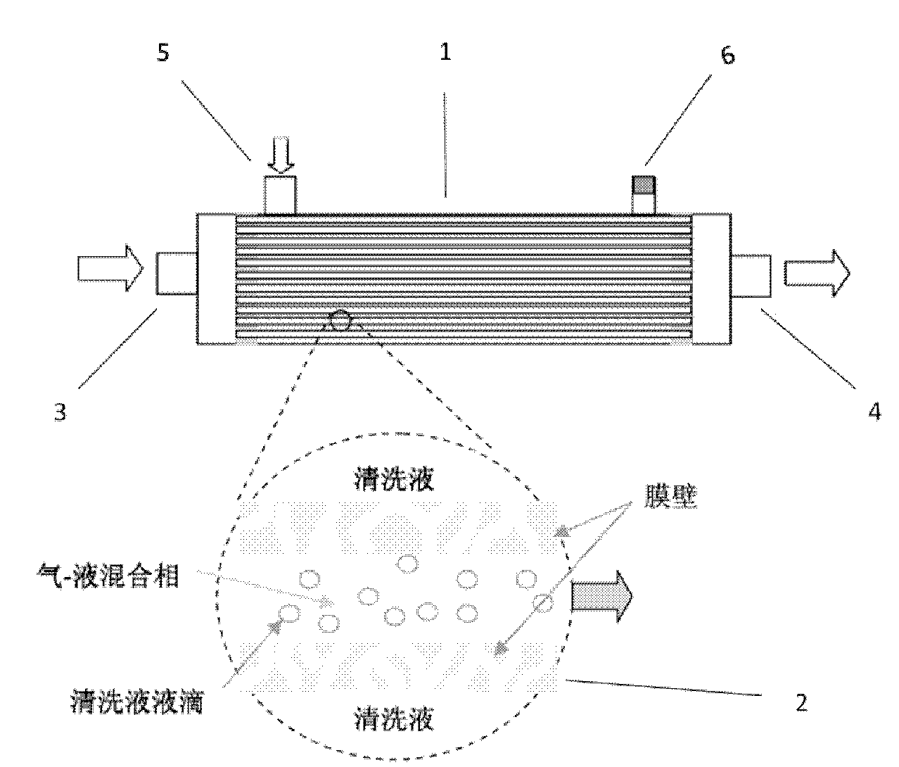
[0026] 1) Heat clean water as the cleaning liquid to 20°C in the liquid storage tank, and then adjust the flow rate to 100ml / min to enter the shell side of the hollow fiber membrane module. Clean water enters continuously from the inlet 5 of the shell side of the hollow fiber membrane module, flows out from the outlet 6 of the shell side and is drained away without recycling.

[0027] 2) Close the inlets 3 and 6, the aforementioned steps are the same as 1), the cleaning liquid enters from the hollow fiber ultrafiltration membrane module shell side inlet 5, flows out from the tube side outlet 4, and does not recycle;

[0028] Switch the flow direction valve, close the inlets 4 and 5, the aforementioned steps are the same as 1), the cleaning liquid enters from the shell side inlet 6 of the hollow fiber ultrafiltration membrane module, flows out from the tube side outlet 3, and is not recycled;

[0029] Repeat process 2) three times.

[0030] 3) The inlet 5 of the shell side is ...

Embodiment 2

[0037] 1) Heat clean water as the cleaning liquid to 20°C in the liquid storage tank, and then adjust the flow rate to 100ml / min to enter the shell side of the hollow fiber membrane module. Clean water enters continuously from the inlet 5 of the shell side of the hollow fiber membrane module, flows out from the outlet 6 of the shell side and is drained away without recycling.

[0038] 2) Close the inlets 3 and 6, the aforementioned steps are the same as 1), the cleaning liquid enters from the hollow fiber ultrafiltration membrane module shell side inlet 5, flows out from the tube side outlet 4, and does not recycle;

[0039] Switch the flow direction valve, close the inlets 4 and 5, the aforementioned steps are the same as 1), the cleaning liquid enters from the shell side inlet 6 of the hollow fiber ultrafiltration membrane module, flows out from the tube side outlet 3, and is not recycled;

[0040] Repeat process 2) three times.

[0041] 3) The inlet 5 of the shell side is ...

Embodiment 3

[0048] 1) Heat clean water as the cleaning liquid to 20°C in the liquid storage tank, and then adjust the flow rate to 100ml / min to enter the shell side of the hollow fiber membrane module. Clean water enters continuously from the inlet 5 of the shell side of the hollow fiber membrane module, flows out from the outlet 6 of the shell side and is drained away without recycling.

[0049] 2) Close the inlets 3 and 6, the aforementioned steps are the same as 1), the cleaning liquid enters from the hollow fiber ultrafiltration membrane module shell side inlet 5, flows out from the tube side outlet 4, and does not recycle;

[0050] Switch the flow direction valve, close the inlets 4 and 5, the aforementioned steps are the same as 1), the cleaning liquid enters from the shell side inlet 6 of the hollow fiber ultrafiltration membrane module, flows out from the tube side outlet 3, and is not recycled;

[0051] Repeat process 2) three times.

[0052] 3) The inlet 5 of the shell side is ...


PUM


Abstract

The invention relates to a method for cleaning filtering membrane modules, which comprises the following steps: high-pressure gas at 0.15MPa-0.5MPa with flow rate of 1L / min-10L / min and cleaning fluid at 10 DEG C-50 DEG C with flow rate of 100mL / min-1000mL / min are respectively applied to two sides of a membrane, the cleaning fluid can permeate through membrane holes under the action of pressure and bring away various contaminants attached to the walls of the membrane holes to the other side, and then is processed into small drops partially at 10m / s by high-pressure gas at the other side, so that great partial shear force is generated to continuously impact the surface of the membrane for impacting, flushing, loosening and separating the various contaminants attached on the surface of the membrane, thereby the effective cleaning effect is achieved. In the method, the specific gas-liquid mixed phase flow is fully utilized to effectively restore the intrinsic separation function of the membrane, so that the service life of the membrane is greatly prolonged and the characteristics of high efficiency, energy conservation and environment protection are achieved.

Description

technical field [0001] The invention relates to a cleaning method suitable for filter membrane components, that is, a method for cleaning various pollutants on the surface of the membrane and in the pores of the membrane through the turbulent flow of the gas-liquid mixed phase to restore the performance of the membrane. Background technique [0002] Membrane separation is a purely physical separation method with low energy consumption and high efficiency. It is a green, energy-saving and environmentally friendly separation technology. It uses a membrane with selective permeability as the separation medium, and the membrane wall is densely covered with micropores. The stock solution passes through one side of the membrane under a certain pressure, and the solvent and small molecular solute pass through the membrane wall to become the filtrate, while the larger molecular solute is intercepted by the membrane, so as to achieve the purpose of material separation and concentratio...

Claims


Application Information

Patent Timeline
Patent Type & Authority Applications(China)
IPC IPC(8): B01D65/02
Inventor 邵嘉慧乔玉柏
Owner SHANGHAI JIAO TONG UNIV
Why Eureka
Try Eureka