
Construction method for complex geological section earth pressure balance shield passing middle air shaft

A technology of earth pressure balance shield tunneling and construction method, which is applied in infrastructure engineering, artificial islands, water conservancy projects, etc. It can solve the problems of mud and sand pouring into wind shafts, shield buried, ground subsidence, etc., to avoid engineering accidents and cost Low, the effect of ensuring safety

Active Publication Date: 2011-08-10
URBAN MASS TRANSIT ENG CO LTD OF CHINA RAILWAY 11TH BUREAU GRP
View PDF0 Cites 29 Cited by
  • Summary
  • Abstract
  • Description
  • Claims
  • Application Information

AI Technical Summary

Problems solved by technology

The jet grouting pile cannot achieve the water-stop effect in such a thick sand layer, and it is bound to form a hydraulic connection channel. Once the cave door is opened, a large amount of mud and sand will flow into the wind shaft, causing a large area of ​​ground subsidence, and serious It will cause the shield tunnel to be buried in major engineering accidents, and the shield tunnels in Nanjing and Tianjin subways are flooded, all of which are caused by this.

Method used


Image

  • Construction method for complex geological section earth pressure balance shield passing middle air shaft
  • Construction method for complex geological section earth pressure balance shield passing middle air shaft
  • Construction method for complex geological section earth pressure balance shield passing middle air shaft

Examples


Embodiment Construction

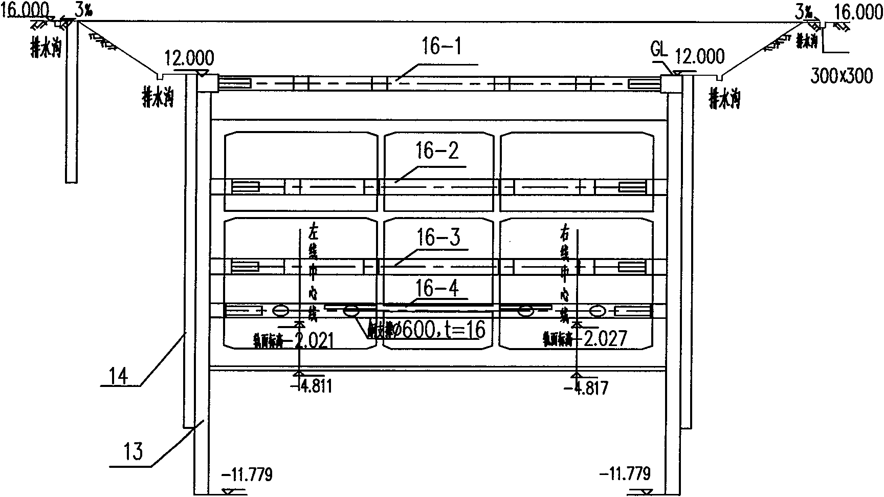
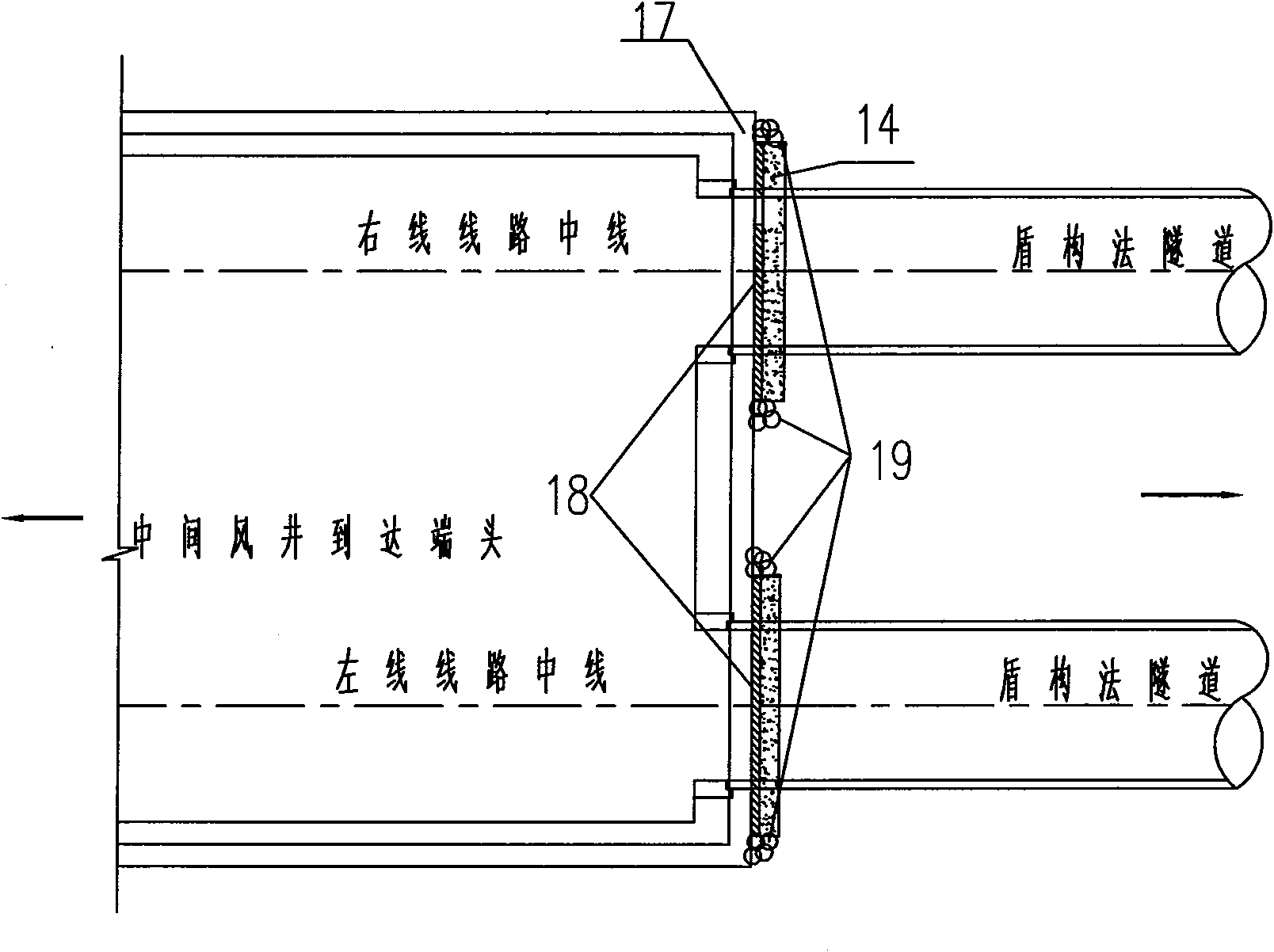
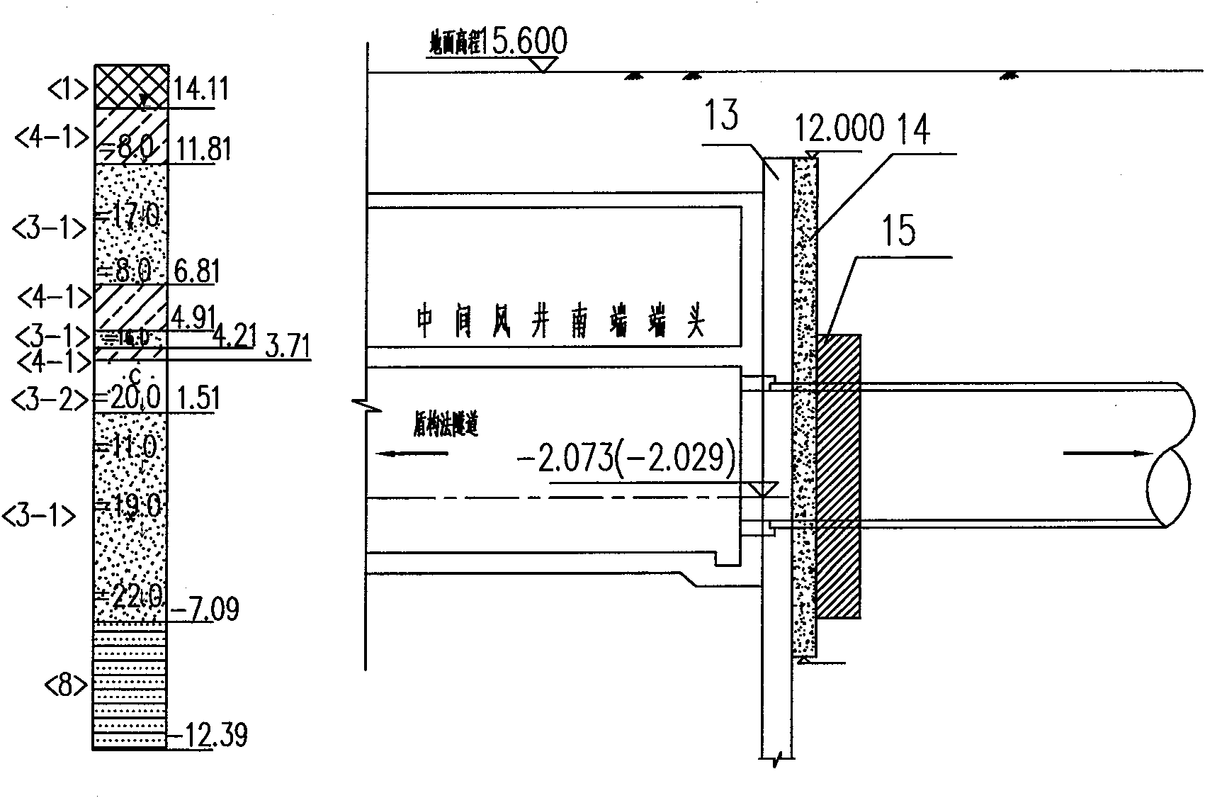
[0032] The concrete implementation method of the present invention is: adopt 800mm thick underground reinforced concrete continuous wall 13 to the enclosure structure of the middle wind shaft, go deep into the bedrock 4m, adopt I-shaped steel joint 28 between each width of the continuous wall (referring to Fig. 4 for the position of I-shaped steel) . The enclosure structure is provided with the first concrete support 16-1, the second concrete support 16-2, the third concrete support 16-3, and the fourth concrete waist beam steel support 16-4, arranged from top to bottom (see Figure 5 ). The liquefied sand layer under the structural floor is reinforced with ¢600 deep-layer mixing piles 15, arranged at a distance of 1000 mm from each other. 800mm thick C20 plain concrete continuous wall 14 is used to seal the entrance on the outside of the enclosure structure at the arrival and departure ends of the left and right lines, each with a width of 9.4m and a depth of 2m into the bed...


PUM


Abstract

The invention discloses a construction method for a complex geological section earth pressure balance shield passing a middle air shaft. The construction method for a middle air shaft enclosure structure at the shield passing position comprises the following steps of: pouring a continuous middle air shaft enclosure wall, arranging four concrete supports on the enclosure wall, and reinforcing deep stirring piles of structural bottom plates; and constructing a plain concrete continuous wall on the outer side of the end enclosure structure to block a tunnel portal. A backfilling method comprises the following steps of: backfilling plastic concrete in a range of 3 meters, close to the tunnel portal, and backfilling cement stabilizing soil at the middle position. The construction method also comprises the following steps of: casting the structural concrete bottom plates, casting a side wall of a negative second layer to the position of 50 centimeters below the third support, performing horizontal hole prospection on the tunnel portal part, detaching the third support, and casting a structural concrete side wall to the position of 50 centimeters below a middle plate. Collapse accidents of the tunnel portal and serious safety accidents when an electrical park brake (EPB) shield reaches and a shield machine is buried can be effectively avoided under complex geological conditions; and secondary departure of the shield machine in the middle air shaft and related risks caused by the secondary departure can be avoided.

Description

technical field [0001] The invention relates to a construction method for an intermediate air shaft of a subway tunnel, in particular to a construction method for an earth pressure balance shield passing through an intermediate air shaft for complex geological sections. Background technique [0002] According to the investigation, when the Earth Pressure Balance shield (EPB shield) in a section of the Nanjing Metro arrived at the station, the silty sand layer above the tunnel poured into the station and the tunnel due to insufficient reinforcement at the arrival end. As a result, the hard crust on the ground collapsed in a large area, and the formed shield tunnel was smashed to more than 150 meters, and the shield machine was buried, causing a major safety accident. If it is not in place, after the hole is broken, a large amount of mud and sand will flow into the originating shaft, resulting in serious consequences of the shield machine being buried in the originating shaft....

Claims


Application Information

Patent Timeline
Patent Type & Authority Applications(China)
IPC IPC(8): E02D29/02E02D3/02
Inventor 张成徐加兵张平胡军凯黄一峰郑伯霖杜广招马明聪廖剑平
Owner URBAN MASS TRANSIT ENG CO LTD OF CHINA RAILWAY 11TH BUREAU GRP
Learn More