Novel backwashing water intake system for water purification building

A technology for backwashing and water purification building, which is applied in water/sewage multi-stage treatment, water/sludge/sewage treatment, water supply devices, etc. problem, to achieve the effect of significant backwashing effect, saving project cost and saving project investment

Inactive Publication Date: 2011-08-10
浙江净水楼建设投资有限公司
View PDF6 Cites 4 Cited by
  • Summary
  • Abstract
  • Description
  • Claims
  • Application Information

AI Technical Summary

Problems solved by technology

However, because many backwashing pipes are shallowly buried in the filter layer, they are easily washed out in flood seasons, which affects the quality of the project; because many backwashing pipes have a large investment in material costs, processing costs, and installation costs, (see Table 1 for details) ) process is complex; and because the backwash pipe has many turns, not only the process is complicated, but also the flow of backwash water is not smooth; and because the holes or eyes of the backwash pipe are easily blocked by pebbles in the filter layer, the backwash effect is seriously affected

Method used


Image

  • Novel backwashing water intake system for water purification building
  • Novel backwashing water intake system for water purification building
  • Novel backwashing water intake system for water purification building

Examples


Embodiment 1

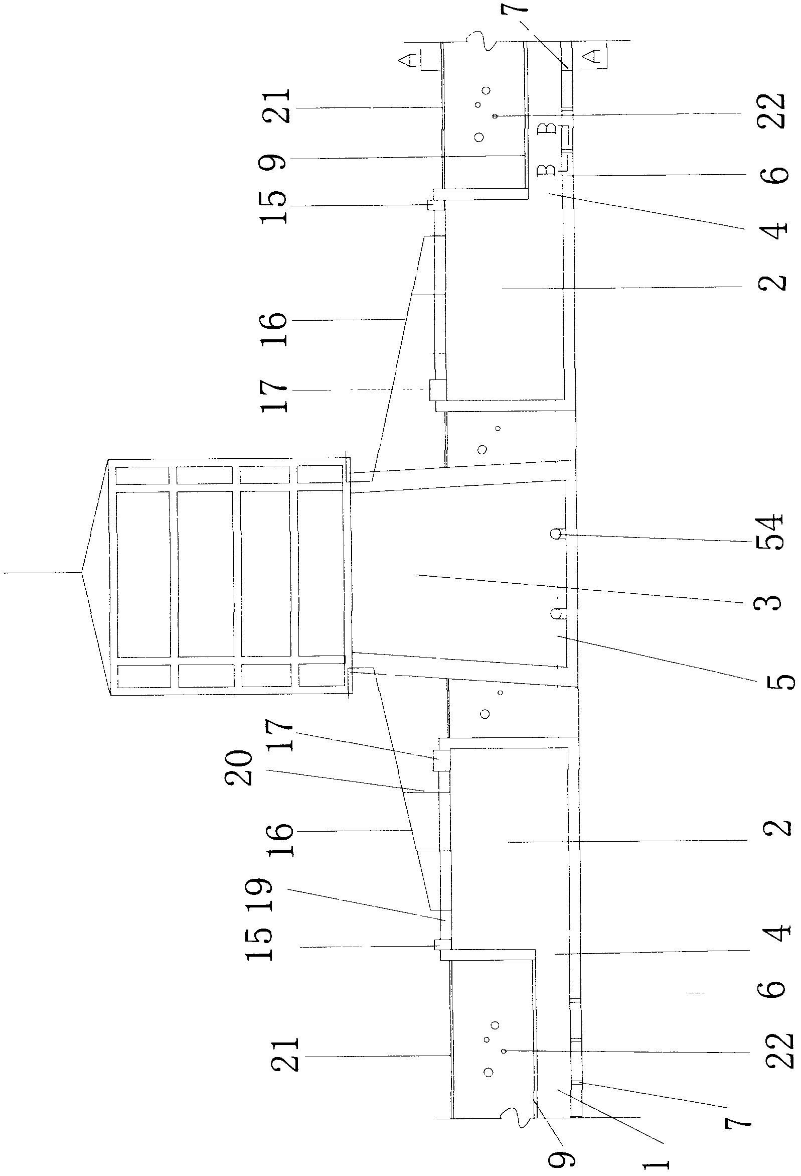
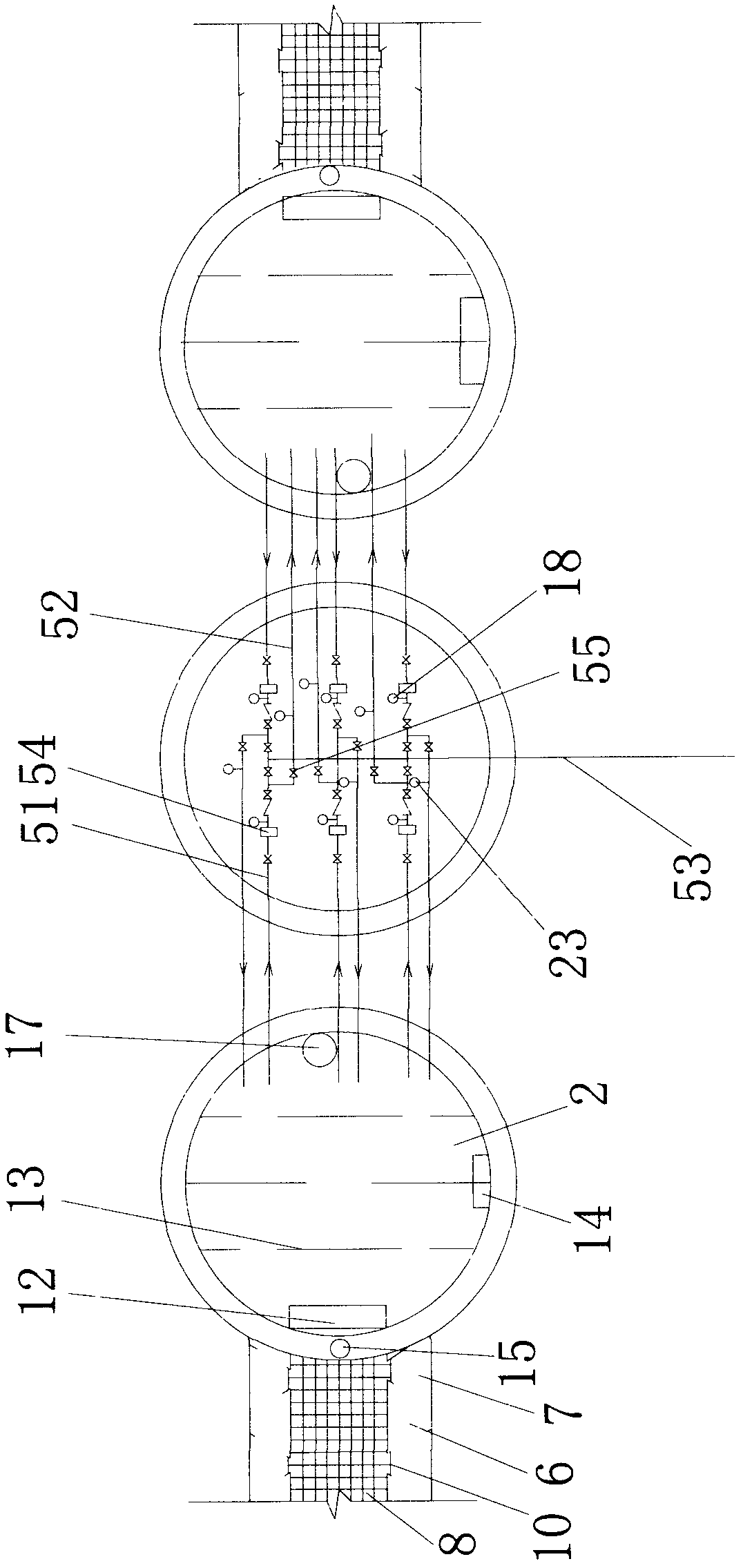
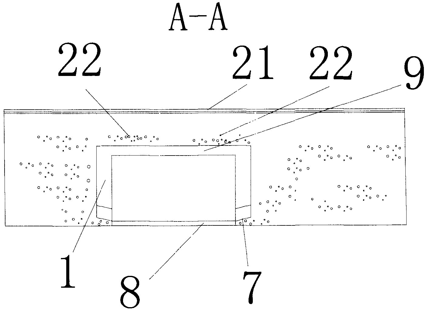
[0026] A kind of water intake system of the novel backwashing of water purification building of the present embodiment, as figure 1 , figure 2 As shown, it includes the infiltration channel 1, the clear water pool 2 and the water purification building 3 directly arranged in the river, and the filter layer 22 is distributed in the river, and the filter layer 22 is sand and pebbles. The filter layer 22 is provided with a filter layer 21, and the filter layer 21 is composed of fine sand and mud. The seepage canal 1 and the clear water pool 2 are communicated through the through hole 4 at the bottom, and the through hole 4 is provided with a gate 12; the clear water pool 2 and the bottom of the water purification building 3 are connected through a pipeline 5, and a diversion wall is installed in the clear water pool 2 13. The clear water tank 2 is provided with inspection holes 14, the reserved holes for adding chlorine in the clear water tank 15, and the clear water tank manhol...

Embodiment 2

[0035] A backwash water intake system in this embodiment, wherein the bell mouth 7 is designed to be inclined downward from the outside to the seepage ditch 1, the inclination angle β is 6°, and the centripetal angle α of the seepage canal bell mouth 1 is 20° °. All the other are with embodiment 1. The contribution of the setting of the inclination angle in this embodiment to the energy-saving effect is shown in Table 2.

Embodiment 3

[0037] A backwashing water intake system of this embodiment, wherein the bell mouth 7 is designed to be inclined downward from the outside to the seepage ditch 1, the inclination angle β is 7°, and the centripetal angle α of the seepage canal bell mouth 1 is 21 °. All the other are with embodiment 1. The contribution of the setting of the inclination angle in this embodiment to the energy-saving effect is shown in Table 2.


PUM


Abstract

The invention discloses a novel backwashing water intake system for a water purification building. The system comprises an infiltration gallery, a clean water tank and the water purification building directly arranged in a river, wherein the infiltration gallery is communicated with the clean water tank through a bottom through hole; the clean water tank is communicated with the bottom of the water purification building through a pipeline; infiltration gallery bell mouth bases are symmetrically arranged at the bottoms of both sides of the infiltration gallery and are provided with bell mouths; the bell mouths are arranged obliquely downwards from the outside to the inside of the infiltration gallery; the pipeline comprises a water inlet pipe, a backwashing pipe and a water outlet pipe; the water outlet pipe is arranged on the water purification building; a horizontal centrifugal pump is arranged at the bottom of the water purification building; the water inlet pipe is arranged on the horizontal centrifugal pump; one end of the water inlet pipe is communicated with the clean water tank, and the other end of the water inlet pipe is communicated with the water outlet pipe; the backwashing pipe is arranged on the water inlet pipe; and one end of the backwashing pipe is communicated with another clean water tank. The water intake system has the characteristics of high backwashing water flow, high water pressure, capabilities of ensuring the engineering quality and the backwashing effect, saving materials and lowering the construction cost and difficulty in blocking.

Description

technical field [0001] The invention relates to a novel backwashing water intake system for a water purification building. Background technique [0002] The current water purification buildings generally use sand and pebbles in rivers and the filter membranes on the upper layer of sand and pebbles as natural filters. The raw water undergoes biological, physical and chemical effects in nature, and the water quality is clear and transparent without impurities. Meet or exceed the standard of drinking water. It replaces multiple steps such as coagulation, flocculation, mixing, sedimentation, filtration, sewage discharge and sludge disposal in the existing tap water purification process. They are arranged in parallel along the banks of the river. When the pump unit in the water purification building pumps water, the water level in the clear water pool and seepage canal will drop. Due to the effect of pressure conduction, a pressure difference will be generated between the water...

Claims


Application Information

Patent Timeline
Patent Type & Authority Applications(China)
IPC IPC(8): C02F9/02E03B3/04
Inventor 陈先土
Owner 浙江净水楼建设投资有限公司
Why Eureka
Try Eureka