Light irradiation unit

A technology of light irradiation device and condenser lens, which is applied in the direction of exposure device, optics, optical elements, etc. of photo-plate making process, can solve the problems of lack of realizability, and achieve the effect of preventing the reduction of illuminance

Inactive Publication Date: 2015-01-21
USHIO DENKI KK
View PDF4 Cites 0 Cited by
  • Summary
  • Abstract
  • Description
  • Claims
  • Application Information

AI Technical Summary

Problems solved by technology

Moreover, the second light source will be arranged at a position very close to the condenser, that is, near the first light source (lamp) that becomes high temperature when emitting light. Therefore, a large-scale cooling system for cooling the second light source is required. system, thereby lacking the realizability

Method used


Image

  • Light irradiation unit
  • Light irradiation unit
  • Light irradiation unit

Examples


Embodiment Construction

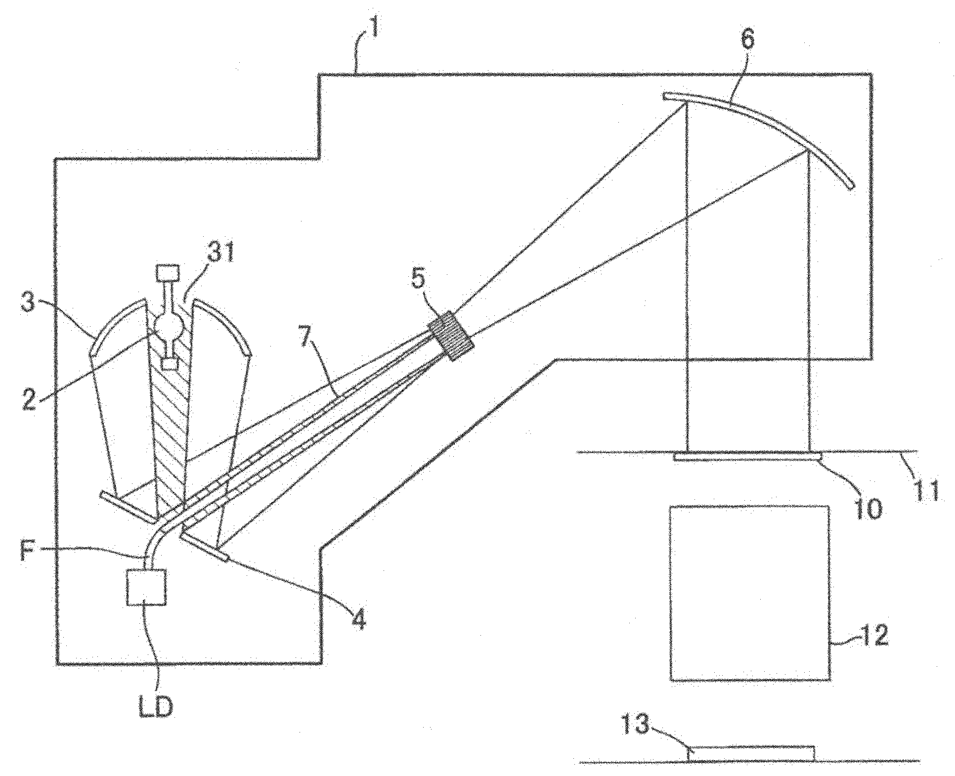
[0049] figure 1 The configuration of the light irradiation device of the present invention used in the light source device of the light exposure device is shown.

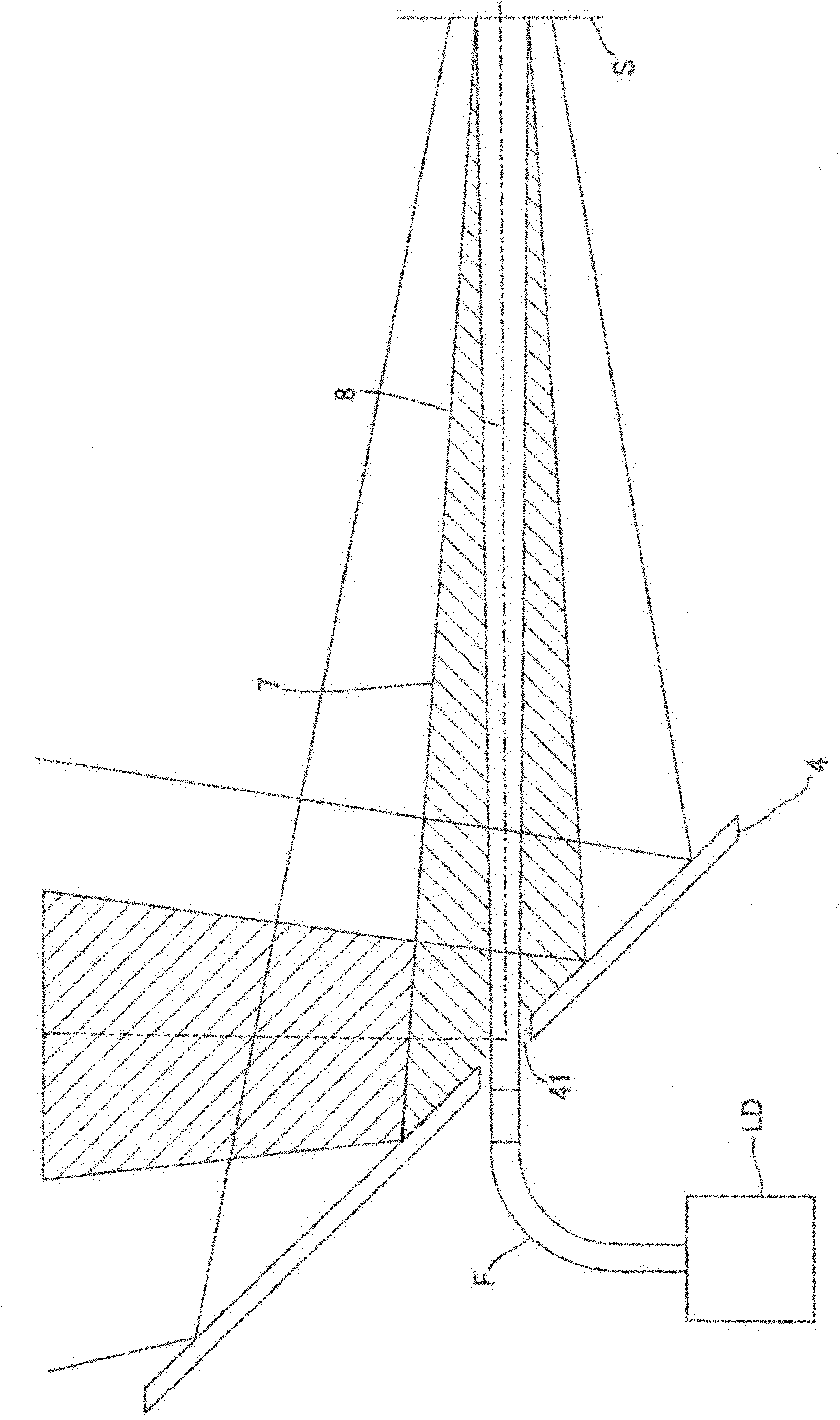
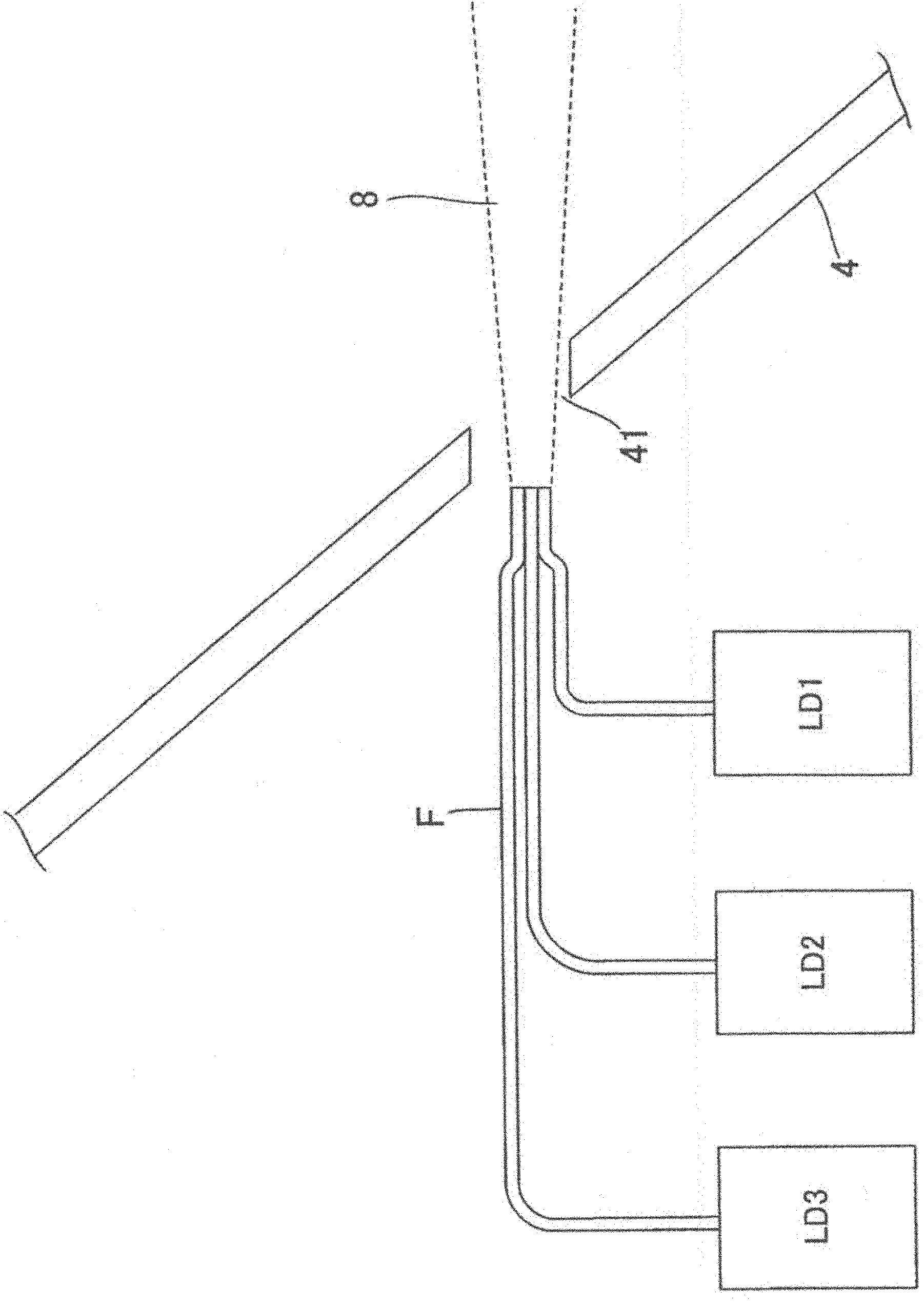
[0050] The light irradiation device of the present invention is basically the same as the plane mirror 4 that turns the optical path back and the second light source disposed on the back side thereof. Figure 4 have the same structure.

[0051] The light irradiation device 1 has a lamp 2 that radiates light including ultraviolet rays, a condenser mirror 3 with an elliptical cross section that condenses the light emitted from the lamp 2, a plane mirror 4 that folds the optical path, and a surface (light irradiation surface) 11 on which the light is irradiated. An integrated lens (fly-eye lens) 5 for making the illuminance distribution uniform, a collimating mirror 6 for reversing the optical path of the light emitted from the integrated lens 5 and making the incident light parallel and emitted.

[0052] The lamp 2 ...


PUM


Abstract

The invention relates to a light irradiation unit, which guides the light from a second light source to an area without light from a first light source where the light from the second light is synthesized with the light form the first light source. In the light irradiation unit, the light from the first light source is synthesized with the second light source in a manner that the light emitted from the first light source is reduced. The light from the first light source is reflected in a direction of an integrated optical element on a plane mirror. A through hole is disposed at the area with weak radiation encircled by the light radiation from the first light source. The light from the second light source is guided from the through hole. Suppose the second light source is a laser diode. The light from the laser diode is guided from the back side of the plane mirror through the through hole.

Description

technical field [0001] The present invention relates to a light irradiation device as a light source device of an exposure device used in the manufacture of semiconductor integrated circuits, liquid crystal display elements, and the like. Background technique [0002] Figure 4 It shows the structure of the light irradiation apparatus used for the light source apparatus of the exposure apparatus of the prior art. [0003] The light irradiation device 1 has a lamp 2 that radiates light including ultraviolet rays, a condenser mirror 3 that condenses the light emitted from the lamp 2 and has an elliptical cross section, a plane mirror 4 that turns the optical path back, and places a surface on which the light is irradiated (light irradiation surface). 11 An integrated lens (also called a fly-eye lens) with uniform illumination distribution 5, a collimating mirror 6 that returns the optical path of the light exiting from the integrated lens and makes the incident light parallel ...

Claims


Application Information

Patent Timeline
Patent Type & Authority Patents(China)
IPC IPC(8): G03F7/20G02B27/09
CPCG02B27/1006G03F7/2004G03F7/2008G03F7/7055H01L21/0275
Inventor 仲田重范
Owner USHIO DENKI KK
Why Eureka
Try Eureka