Multi-axis motion control device based on versa module Euro-card (VME) bus

A multi-axis motion and control device technology, applied in digital control, electrical program control, etc., can solve the problem that the speed of the interface chip cannot meet the multi-axis control.

Inactive Publication Date: 2011-08-10
HARBIN INST OF TECH
View PDF4 Cites 10 Cited by
  • Summary
  • Abstract
  • Description
  • Claims
  • Application Information

AI Technical Summary

Problems solved by technology

[0004] The purpose of the present invention is to provide a multi-axis motion control device based on the VME bus to solve the probl

Method used


Image

  • Multi-axis motion control device based on versa module Euro-card (VME) bus
  • Multi-axis motion control device based on versa module Euro-card (VME) bus
  • Multi-axis motion control device based on versa module Euro-card (VME) bus

Examples


specific Embodiment approach 1

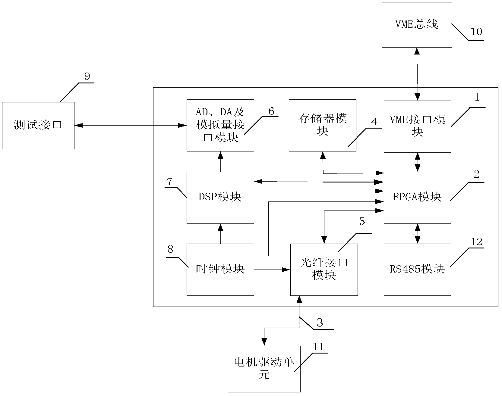
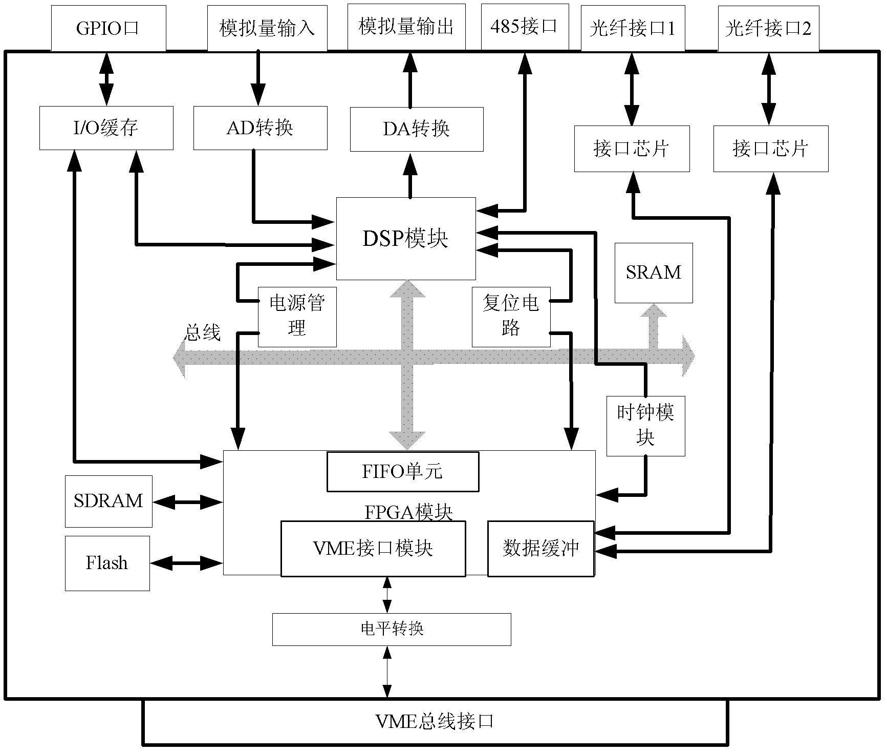
[0008] Specific implementation mode one: combine figure 1 and figure 2 Describe this embodiment, this embodiment comprises VME interface module 1, FPGA module 2, optical fiber 3, memory module 4, optical fiber interface module 5, DSP module 7, clock module 8, motor drive unit 11 and VME bus 10, VME interface module One data exchange end of 1 is connected with VME bus 10, the other data exchange end of VME interface module 1 is connected with one data exchange end of FPGA module 2, and the other data exchange end of FPGA module 2 is connected with the data exchange end of memory module 4 Connected, another data exchange end of FPGA module 2 is communicated with the data exchange end of DSP module 7, the fourth data exchange end of FPGA module 2 is communicated with a data exchange end of optical fiber interface module 5, and the control output end of DSP module 7 Be connected to the control input end of FPGA module 2, an output end of clock module 8 is connected in the clock ...

specific Embodiment approach 2

[0014] Specific implementation mode two: combination figure 1 Describe this embodiment, the difference between this embodiment and Embodiment 1 is that it also includes an RS485 module 12, and a data exchange port of the RS485 module 12 communicates with the fifth data exchange port of the FPGA module 2. Other components and connections are the same as those in Embodiment 1.

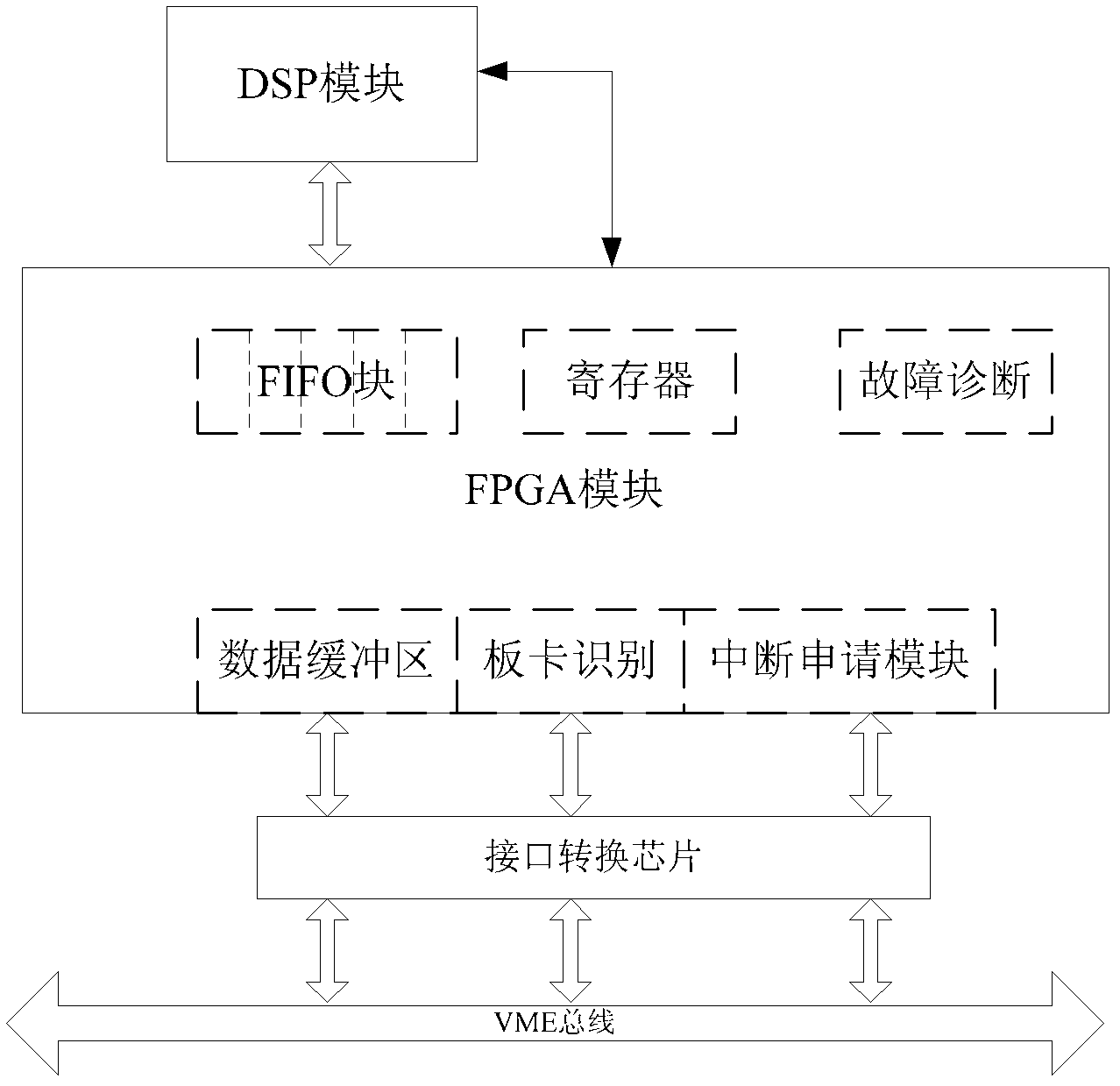
[0015] The RS485 module 12 is used to communicate with other motion control devices or data acquisition units of the VME industrial computer, so as to ensure the synchronization between various motion control devices and data acquisition units when multiple devices are used in conjunction. The motion control device has the function of automatically identifying the device number, which overcomes the shortcomings of traditional control devices that require jumpers or dial switches to identify the control device, and is convenient for plug and play. The interface module of the motion control device adopts ...

specific Embodiment approach 3

[0017] Specific implementation mode three: combination figure 1 Describe this embodiment, the difference between this embodiment and Embodiment 1 is that it also includes AD, DA and analog quantity interface module 6 and test interface 9, the data exchange end of AD, DA and analog quantity interface module 6 and the connection of test interface 9 The data exchange end is connected, and the other control output end of the DSP module 7 is connected to the control input end of the AD, DA and analog quantity interface module 6 . Other components and connections are the same as those in Embodiment 1.

[0018] DSP module 7 realizes the control of AD and DA modules. In order to ensure the accuracy requirements of system debugging, both AD and DA adopt 16-bit resolution chips. The DA module can realize ±10V analog output through programming, and the AD module can realize ±10V analog output. For 10V analog acquisition, due to the high cost of the AD chip, in order to reduce the cost, ...


PUM


Abstract

The invention relates to a motion control device based on a versa module Euro-card (VME) bus, in particular to a multi-axis motion control device based on the VME bus, which solves the problem that a speed cannot meet multi-axis control because most of conventional VME interface chips are early products. The multi-axis motion control device comprises a VME interface module, a field programmable gate array (FPGA) module, optical fibres, a memory module, an optical fibre interface module, a digital signal processor (DSP) module, a clock module, a motor driving unit and the VME bus, wherein a data exchange end of the VME interface module is communicated with the VME bus; a fourth data exchange end of the FPGA module is communicated with the data exchange end of the optical fibre interface module; a control output end of the DSP module is connected to a control input end of the FPGA module; another output end of the clock module is connected to a clock input end of the optical fibre interface module; and another data exchange end of the optical fibre interface module is communicated with the data exchange end of the motor driving unit through the optical fibres for realizing multi-axis motion control.

Description

technical field [0001] The invention relates to a motion control device based on VME bus. Background technique [0002] With the development of numerical control technology, the complexity of the controlled system is constantly increasing, and the requirements for motion controllers are becoming more and more stringent. Due to the limitation of hardware (such as the main control chip MCU), the traditional control device can only realize the movement of several motion axes in order to meet the small enough servo cycle (usually within 100us) in high-speed and high-precision motion control. Even only single-axis movement can be completed. However, many CNC systems today have developed from single-axis motion to joint motion of more than a dozen axes, and the system has higher and higher requirements for control accuracy and speed. For example, in the semiconductor manufacturing process, the workpiece table often needs The time produces a speed large enough to ensure the work ...

Claims


Application Information

Patent Timeline
IPC IPC(8): G05B19/414
Inventor 陈兴林姜晓明杜威王程郝中洋
Owner HARBIN INST OF TECH
Why Eureka
Try Eureka