Electromagnetic suspension rotor micromotor with internally embedded stator

An electromagnetic levitation and stator internal technology, which is applied in the manufacture of stator/rotor bodies, electrical components, magnetic attraction or thrust holding devices, etc., can solve the problems of increasing the complexity of control circuits, poor stability of suspension anti-interference, and variable stiffness of suspensions. Tonality is not good and other problems, to achieve the effect of increasing self-stability

Inactive Publication Date: 2011-08-10
SHANGHAI JIAO TONG UNIV
View PDF4 Cites 6 Cited by
  • Summary
  • Abstract
  • Description
  • Claims
  • Application Information

AI Technical Summary

Problems solved by technology

[0005] But the above-mentioned technology has the following deficiencies: 1. Two high-frequency currents with different frequencies need to pass through the series coil, which increases the complexity of the control circuit; 2. The stable levitation drive electromagnetic field and the rotation drive electromagnetic field overlap in space Together, so the mutual interference between them is increased; 3. The rotating electromagnetic field is distributed in the entire radius and length direction, but the rotating electromagnetic field at the larger radius plays the most role; 4. Since it can only be suspended on one side Drive, so the suspension stability of the whole device is not good, and the stable suspension anti-interference performance is poor; 5. With the increase of the current in the double-layer stable suspension coil, the suspension height of the micro-rotor increases, so the lateral stiffness of the suspension body is not adjustable. it is good
However, the electromagnetic levitation rotor micromotor with this structure has a closed rotor structure, which is not suitable for manufacturing by microfabrication methods.

Method used


Image

  • Electromagnetic suspension rotor micromotor with internally embedded stator
  • Electromagnetic suspension rotor micromotor with internally embedded stator
  • Electromagnetic suspension rotor micromotor with internally embedded stator

Examples


Embodiment Construction

[0019] The embodiments of the present invention are described in detail below. This embodiment is implemented on the premise of the technical solution of the present invention, and detailed implementation methods and specific operating procedures are provided, but the protection scope of the present invention is not limited to the following implementation example.

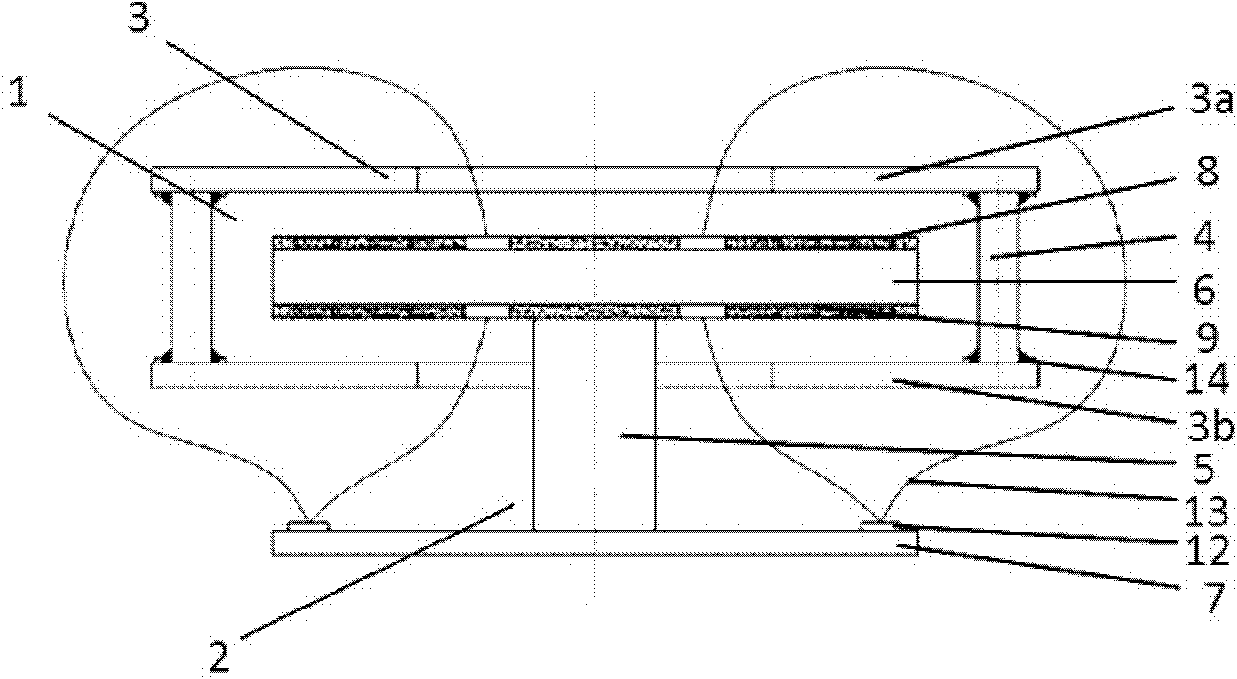
[0020] Such as figure 1 with figure 2 As shown, this embodiment includes: a rotor 1 and a stator 2 rotatably arranged in the rotor 1, wherein:

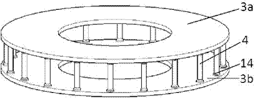
[0021] The rotor 1 includes: a rotor disc 3 and a connecting column 4, wherein: the two ends of a plurality of connecting columns 4 are vertically fixedly connected with two rotor discs 3 respectively,

[0022] The rotor disc 3 is composed of a rotor upper disc 3a and a rotor lower disc 3b of the same structure, wherein: the rotor upper disc 3a and the rotor lower disc 3b are fixedly connected to the two ends of the coupling column 4 and form a box-shaped micro The rot...


PUM


Abstract

The invention discloses an electromagnetic suspension rotor micromotor with an internally embedded stator in the technical field of micro electro mechanical system, which comprises a rotor and a stator arranged in the rotor in a rotating way. The rotor comprises disc plates of the rotor and connecting columns, wherein the two ends of a plurality of connecting columns are respectively, vertically and fixedly connected with two disc plates of the rotor; the stator comprises supporting columns, a basal body, substrates as well as an upper stator and a lower stator with same structures, wherein the supporting columns are arranged in the circular center of the rotor; moreover, the two ends of the supporting columns are respectively and fixedly connected with the lower stator and the substrates; moreover, the upper stator and the lower stator are respectively and fixedly connected with the upper surface and the lower surface of the basal body. Compared with the prior art, the electromagnetic suspension rotor micromotor with the internally embedded stator is provided with an electromagnetic suspension body, which increases the autostability of the motor.

Description

technical field [0001] The invention relates to a device in the technical field of micro-electro-mechanical systems, in particular to a stator-embedded electromagnetic levitation rotor micro-motor. Background technique [0002] The use of suspension technology can avoid the friction and wear caused by contact, so as to obtain high moving speed or rotation speed, and at the same time avoid the pollution of materials due to contact, so suspension technology is widely used in production or life, such as Maglev trains, electrostatic levitation bearings, electromagnetic levitation smelting technology, electrostatic gyroscopes, etc. Electromagnetic levitation is completely a passive levitation technology, that is, it does not need an external feedback control circuit to achieve autonomous levitation. At the same time, electromagnetic levitation has no strict requirements on the gap between electrodes. Compared with electrostatic levitation, the structure of electromagnetic levitat...

Claims


Application Information

Patent Timeline
Patent Type & Authority Applications(China)
IPC IPC(8): H02N15/00H02K15/02H02K15/10
Inventor 吴校生陈文元张卫平
Owner SHANGHAI JIAO TONG UNIV
Why Eureka
Try Eureka