Stator embedded electromanetic suspension rotor micro motor

An electromagnetic levitation and stator internal technology, which is applied in the field of micro motors, can solve the problems of poor suspension stiffness adjustment, increased control circuit complexity, and poor anti-interference of stable suspension, so as to increase self-stability and reduce design Difficulty, the effect of increasing the area of ​​action

Inactive Publication Date: 2009-12-02
SHANGHAI JIAOTONG UNIV
View PDF6 Cites 2 Cited by
  • Summary
  • Abstract
  • Description
  • Claims
  • Application Information

AI Technical Summary

Problems solved by technology

The planar coil series electromagnetic levitation micro-rotating gyroscope has the following disadvantages: 1. Two high-frequency currents of different frequencies need to pass through the series coil, which increases the complexity of the control circuit; 2. Stable levitation drive electromagnetic field and rotation drive The electromagnetic fields overlap in space, thus increasing the mutual interference between them; 3. The rotating electromagnetic field is distributed in the entire radius and length direction, but the rotating electromagnetic field at a larger radius plays the most role; 4. Because it can only be driven by unilateral suspension, the suspension stability of the whole device is not good, and the stable suspension anti-interference performance is poor; 5. With the increase of the current in the stable suspension coil, the suspension height of the micro-rotor increases, so the lateral stiffness of the suspension poor adjustability
This speed is far from meeting the requirements of high-precision micro-gyro

Method used


Image

  • Stator embedded electromanetic suspension rotor micro motor
  • Stator embedded electromanetic suspension rotor micro motor
  • Stator embedded electromanetic suspension rotor micro motor

Examples


Embodiment Construction

[0013] The embodiments of the present invention are described in detail below in conjunction with the accompanying drawings: the present embodiment is implemented on the premise of the technical solution of the present invention, and detailed implementation methods and processes are provided, but the protection scope of the present invention is not limited to the following implementations example.

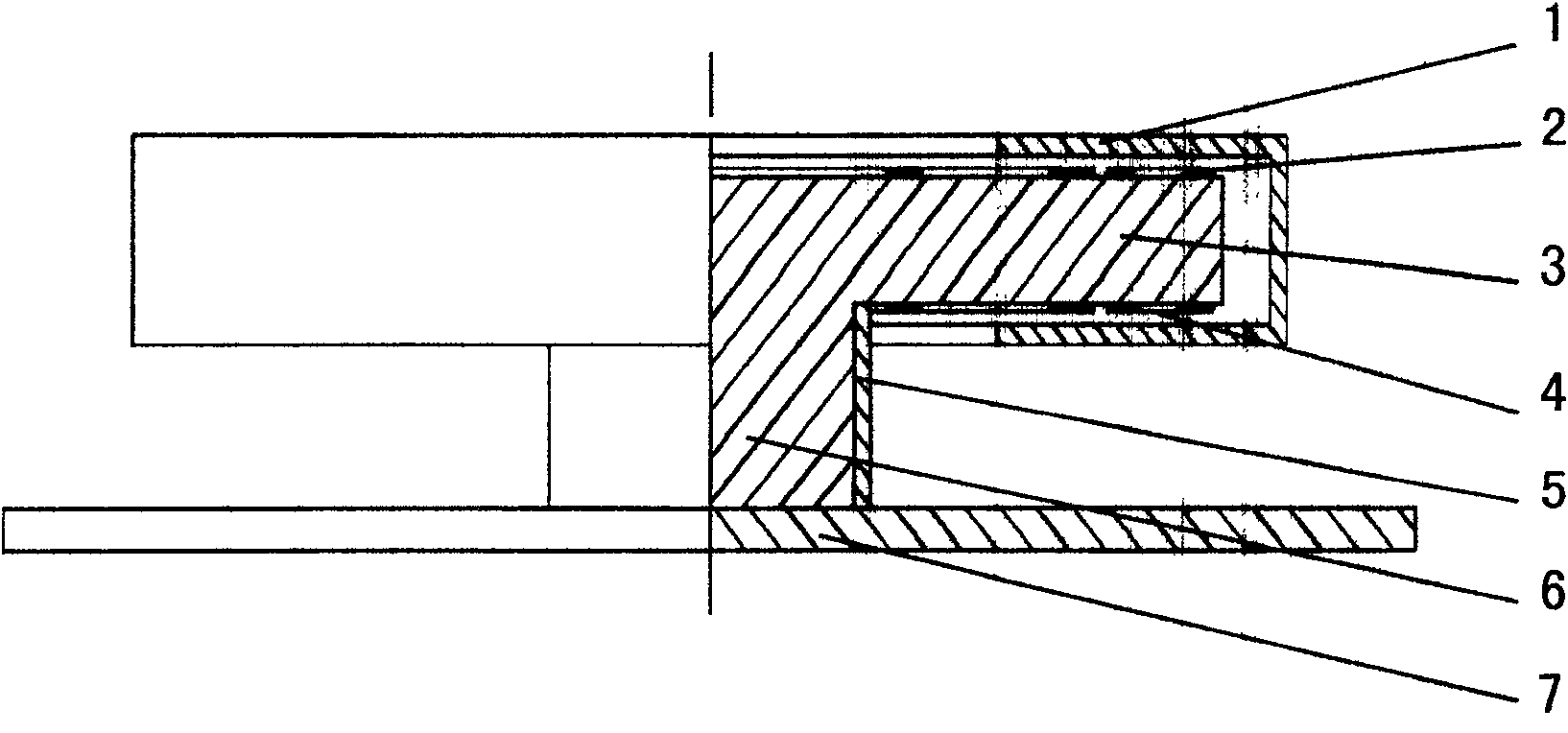
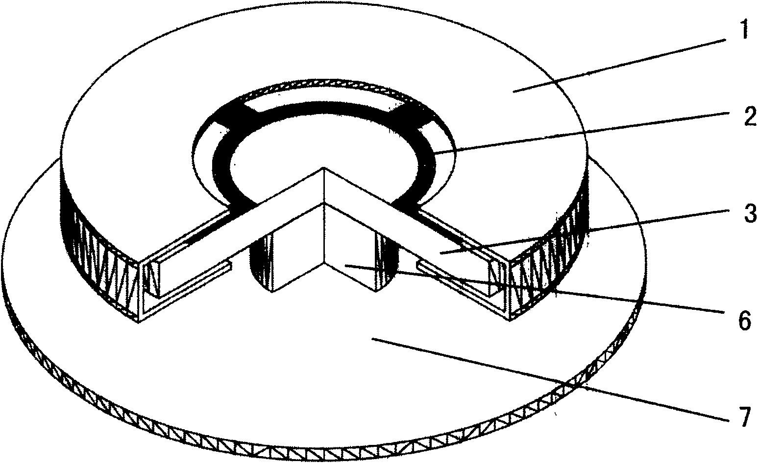
[0014] Such as figure 1 and figure 2 As shown, this embodiment includes: a box-shaped micro-rotor 1 , an upper stator 2 , an intermediate base 3 , a lower stator 4 , leads 5 , an intermediate column 6 , and a lower base 7 .

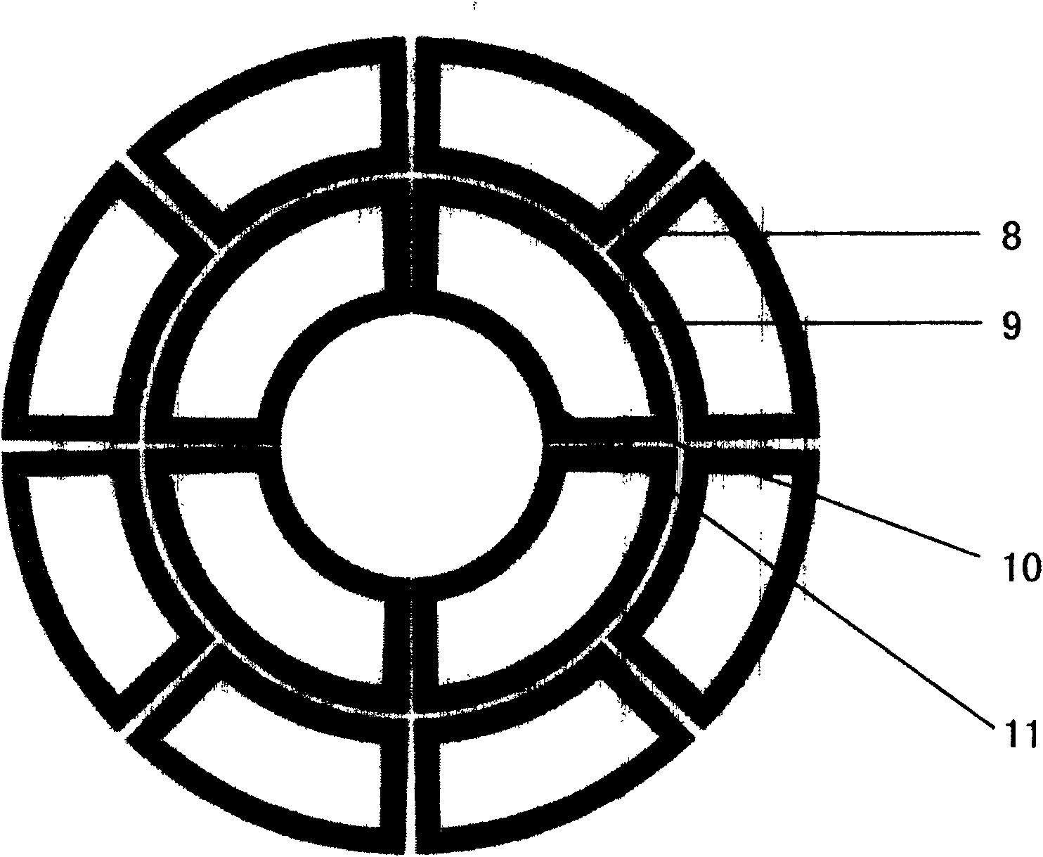
[0015] Such as image 3 As shown, the upper stator 2 and the lower stator 4 are identical, and consist of three parts: a rotating coil 8 , an outer coil 9 of a stable levitation coil, an inner coil 11 of a stable levitation coil, and a connecting wire 10 . The connection relationship is: the upper stator 2 and the lower stator 4 are both arranged on the in...


PUM


Abstract

The utility model relates to a stator-embedded electromagnetic levitation rotor micro-motor, which belongs to the technical field of micro-electro-mechanical systems. In the present invention, both the upper stator and the lower stator are arranged on the intermediate base, and form a fixed connection with the intermediate base, the box-shaped micro-rotor is in the shape of a hollow circular box, and the box-shaped micro-rotor is under the electromagnetic force of the upper stator and the lower stator It is stably suspended on the outer edge of the intermediate base. There are eight rotating coils distributed on the intermediate base. They are divided into two groups of four-phase coils. When high-frequency alternating current passes through the rotating coils, the current phase difference of adjacent coils is 90 degrees, so that , A rotating magnetic field is formed in the space where the box-shaped micro-rotor is located, and the box-shaped micro-rotor generates a rotating torque under the action of the rotating magnetic field to make it rotate at a high speed. The present invention adopts a box-shaped micro-rotor and a built-in stator structure, which can increase the suspension stiffness and lateral stability stiffness of the suspended micro-rotor, and at the same time, the intermediate base can limit the position of the micro-rotor when the box-shaped micro-rotor is not working .

Description

technical field [0001] The invention relates to a micro-motor in the field of micro-electromechanical technology, in particular to a stator-embedded electromagnetic levitation rotor micro-motor. Background technique [0002] The use of suspension technology can avoid the friction and wear caused by contact, so as to obtain high moving speed or rotation speed, and at the same time avoid the pollution of materials due to contact, so suspension technology is widely used in production or life, such as Maglev trains, electrostatic levitation bearings, electromagnetic levitation smelting technology, electrostatic gyroscopes, etc. Electromagnetic levitation is completely a passive levitation technology, that is, it does not need an external feedback control circuit to achieve autonomous levitation. At the same time, electromagnetic levitation has no strict requirements on the gap between electrodes. Compared with electrostatic levitation, the structure of electromagnetic levitation...

Claims


Application Information

Patent Timeline
Patent Type & Authority Patents(China)
IPC IPC(8): H02N15/00H02K7/00H02K7/09
Inventor 吴校生陈文元赵小林
Owner SHANGHAI JIAOTONG UNIV
Why Eureka
Try Eureka