Melt refiner

A purification device and melt technology, applied in stirring devices, charge manipulation, lighting and heating equipment, etc., can solve problems such as product defects, achieve the effects of improving internal quality, preventing temperature drop, improving internal quality and surface quality

Inactive Publication Date: 2013-11-06
NIPPON LIGHT METAL CO LTD
View PDF1 Cites 0 Cited by
  • Summary
  • Abstract
  • Description
  • Claims
  • Application Information

AI Technical Summary

Problems solved by technology

If such non-metallic impurities and hydrogen are contained in the metal melt, it will cause defects in the formed product, so it is not ideal

Method used


Image

  • Melt refiner
  • Melt refiner
  • Melt refiner

Examples


no. 1 approach

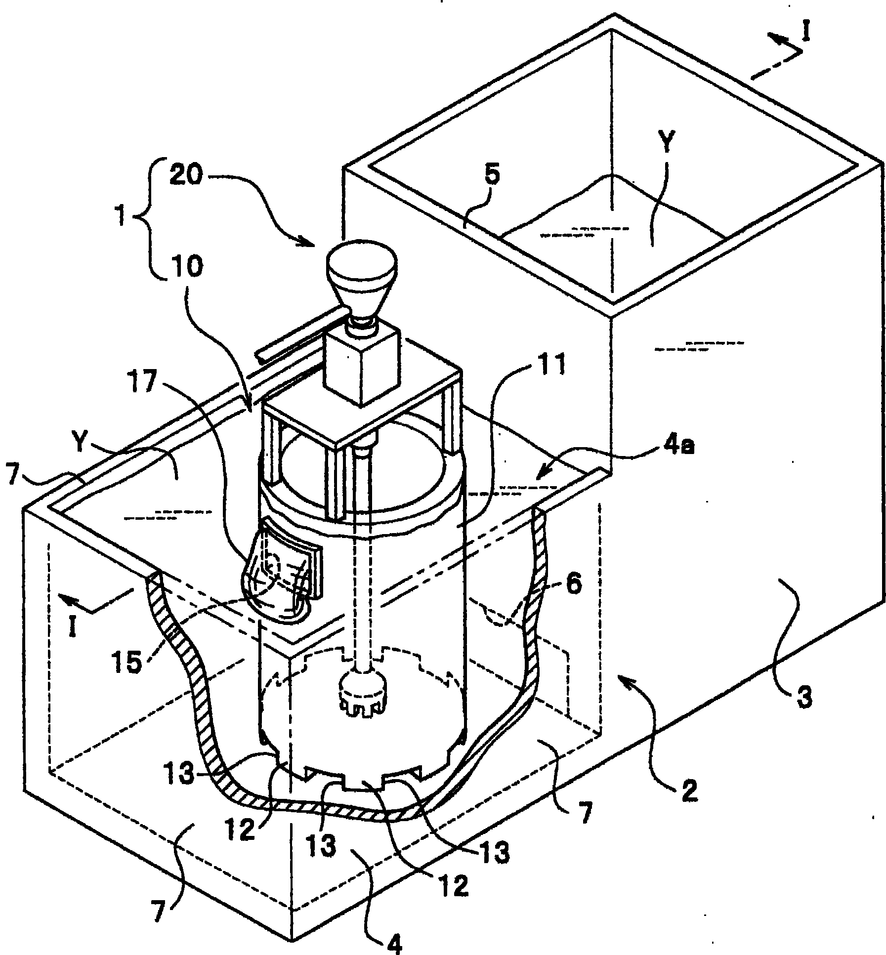
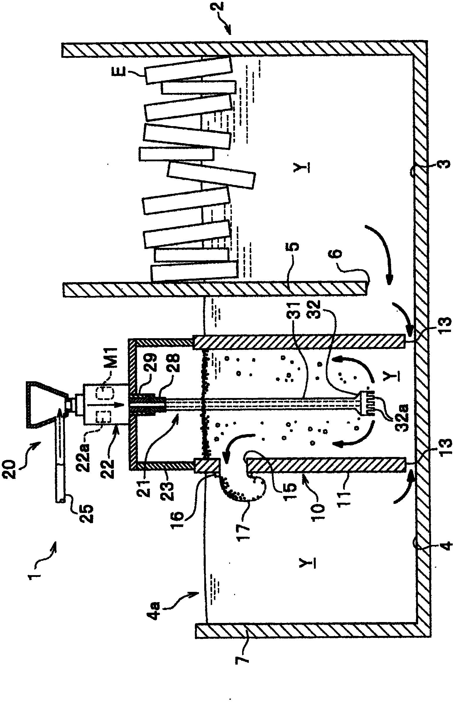
[0036] Embodiments of the present invention will be described in detail with reference to the drawings. Such as figure 1 and figure 2 As shown, in the first embodiment, the case of using the melt purification device 1 in the continuous processing furnace 2 will be described as an example.

[0037] Such as figure 1 and figure 2 As shown, the continuous processing furnace 2 has: a melting furnace 3 for melting an aluminum ingot E, for example; The melting furnace 3 includes a burner (furnace) not shown in the figure, and is heated to 720° C. to 900° C. to melt the aluminum ingot E to generate a molten metal Y.

[0038] The pumping chamber 4 is arranged side by side with the melting furnace 3 via the furnace wall 5 , is provided with a molten metal purification device 1 described later, and holds purified molten metal Y. The pumping chamber 4 corresponds to a "holding chamber" in the claims. Such as figure 2 As shown, a liquid outlet 6 is provided through the lower part...

no. 2 approach

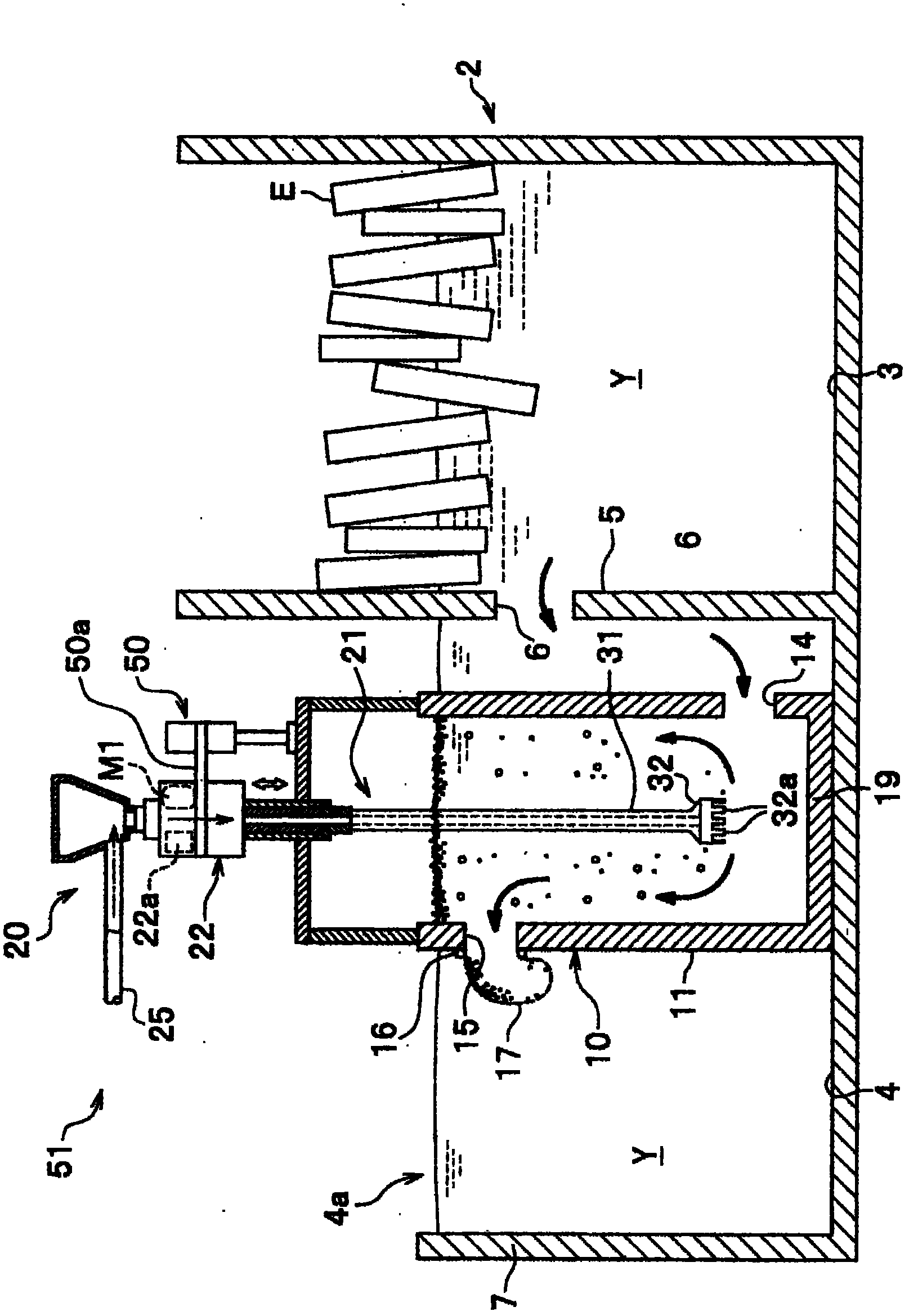
[0064] Next, a second embodiment of the present invention will be described. image 3 It is a cross-sectional view showing the melt purification device and the continuous processing furnace in the second embodiment. Such as image 3 As shown, the melt purification device 51 of the second embodiment differs from the first embodiment in that the bottom 19 is formed on the processing cylinder 10 and that an elevating mechanism 50 for elevating the rotor 21 is provided. In addition, the same code|symbol is attached|subjected to the part common (common) with 1st Embodiment, and description is abbreviate|omitted.

[0065] The melt purification device 51 of the second embodiment mainly includes the processing cylinder unit 10 and the refining device 20 . The processing cylinder 10 has: a circular cylinder 11 in plan view, a bottom 19 formed at the lower end of the cylinder 11, an inlet hole 14 penetrating through the lower part of the cylinder 11, and an outlet penetrating through ...

no. 3 approach

[0073] Figure 4 It is a sectional view showing the melt purification device and the crucible boiler in the third embodiment. In the first and second embodiments, the case where the melt purification device is installed in the continuous processing furnace 2 has been described, but the present invention is not limited to this, and the crucible boiler 82 may be installed as described in the third embodiment. Purification device.

[0074] As described in the third embodiment, in the crucible 82 , the molten metal purifying device 1 may be installed in the holding furnace 84 that melts the ingot and holds the molten metal Y. Thus, the target for installing the molten metal purifying device of the present invention is not limited to the pumping chamber 4 of the continuous processing furnace 2, but may also be the holding furnace 82 that heats and holds the molten metal Y when the molten metal Y is drawn out with a ladle or the like.


PUM


Abstract

A melt refiner (1) which is for use in a ladling chamber (4) (holding chamber) that holds a metal melt (Y) therein and in which the metal melt is subjected to degassing and deslagging to heighten the degree of cleanliness of the metal melt and keep the amount of hydrogen gas small.  With the melt refiner (1), the possibility that a slag generated is drawn up with a ladle or the like is low.  The refiner is characterized by comprising: a cylindrical treating part (10) which is to be disposed in the ladling chamber (4) and has an opening (inlet hole) (13) through which the metal melt (Y) is caused to flow inward and an outlet hole (15) for discharging the melt outward; and a purifier (20) with which the metal melt (Y) inside the cylindrical treating part (10) is subjected to at least either degassing or deslagging.  The refiner is further characterized in that the top of the cylindrical treating part (10) protrudes from the surface of the metal melt (Y) held in the ladling chamber (4).

Description

technical field [0001] The invention relates to a melt purification device for removing non-metal impurities (inclusions) and hydrogen in metal melt. Background technique [0002] A molten metal (melt: molten metal) produced by melting an aluminum ingot or the like has a problem that non-metallic impurities, hydrogen gas, and the like are inevitably contained. If such non-metallic impurities and hydrogen gas are contained in the molten metal, it is not ideal because it will cause defects in the molded product. Therefore, a so-called degassing device is known as a refining device for promoting the separation and removal of non-metallic impurities from molten metal and reducing the amount of hydrogen. [0003] For example, the refining device in Patent Document 1 mainly includes a rotor that rotates in molten metal and a drive unit that drives the rotor. A disc-shaped rotating body is provided below the rotor, and inert gas is ejected from through holes formed in the bottom ...

Claims


Application Information

Patent Timeline
Patent Type & Authority Patents(China)
IPC IPC(8): C22B9/05B22D43/00B22D45/00
CPCB22D11/118B22D11/117C22B21/064B22D43/00C22B9/05F27B14/08F27D3/16F27D27/00B22D45/00
Inventor 仓增幸雄
Owner NIPPON LIGHT METAL CO LTD
Why Eureka
Try Eureka