
Self-light emitting display device

一种显示装置、自发光的技术,应用在有机半导体器件、电气元件、晶体管等方向,能够解决降低光透射率或发光效率等问题,达到降低反射率的效果

Pending Publication Date: 2020-04-07
LG DISPLAY CO LTD
View PDF4 Cites 0 Cited by
  • Summary
  • Abstract
  • Description
  • Claims
  • Application Information

AI Technical Summary

Problems solved by technology

Therefore, the color filter may absorb light other than light within a wavelength range of a predetermined color to be displayed, thereby reducing light transmittance or luminous efficiency

Method used


Image

  • Self-light emitting display device
  • Self-light emitting display device
  • Self-light emitting display device

Examples


Embodiment Construction

[0026] Advantages and features of the present invention and methods for achieving them can be clearly understood by referring to the following description of embodiments and experimental examples in conjunction with the accompanying drawings. The drawings are provided so that the technical spirit of the present invention can be easily understood. Therefore, the technical spirit of the present invention should not be construed as being limited to the accompanying drawings.

[0027] In addition, the subject matter of the present invention may be embodied in various forms. Therefore, the present invention should not be construed as being limited to the following disclosure. Rather, the following disclosure is presented so that this disclosure will be thorough and complete, and will fully convey the scope of the inventive subject matter to those of ordinary skill in the art. The invention should be limited only by the scope of the appended claims.

[0028] Detailed descriptions...


PUM


Abstract

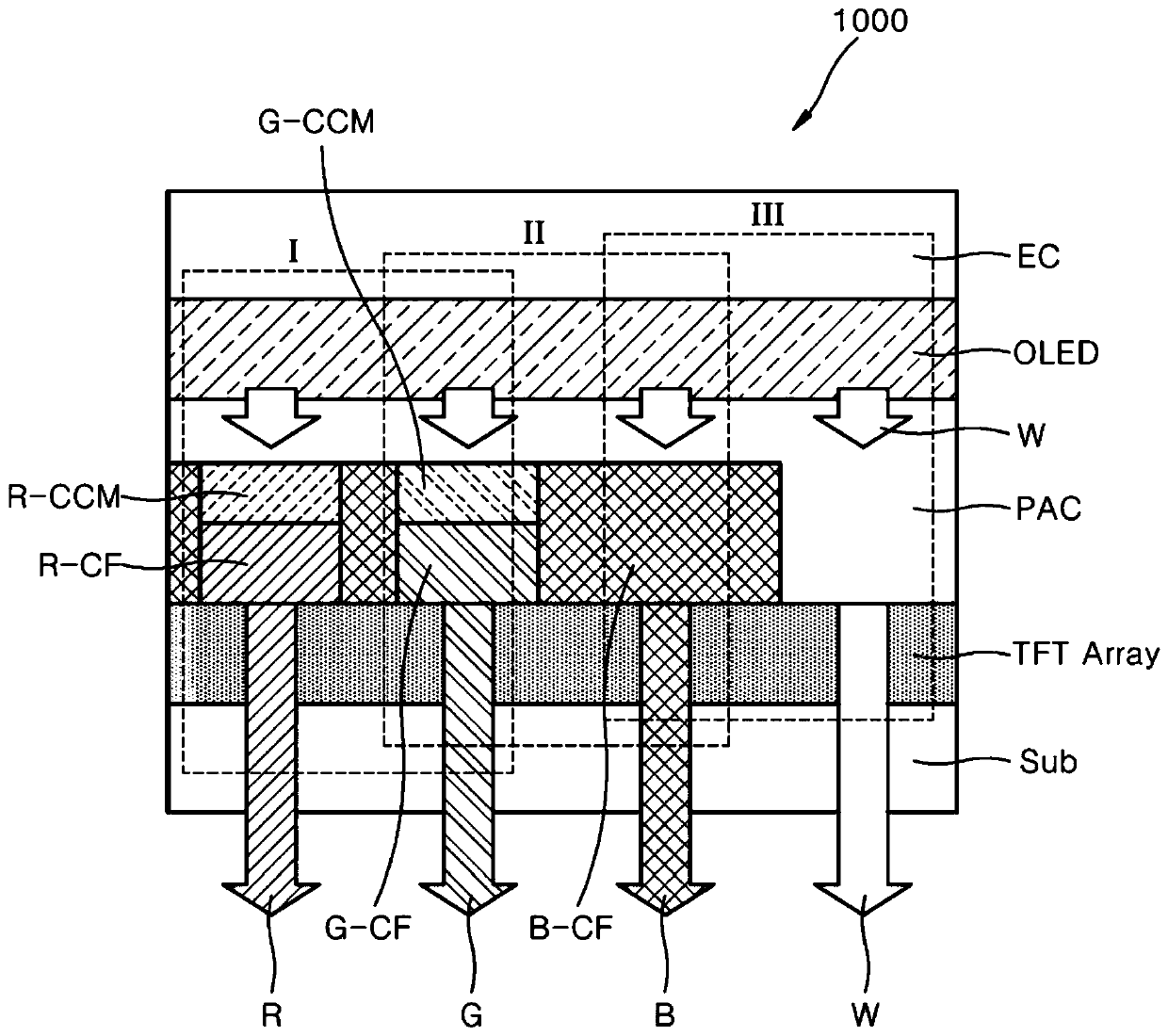
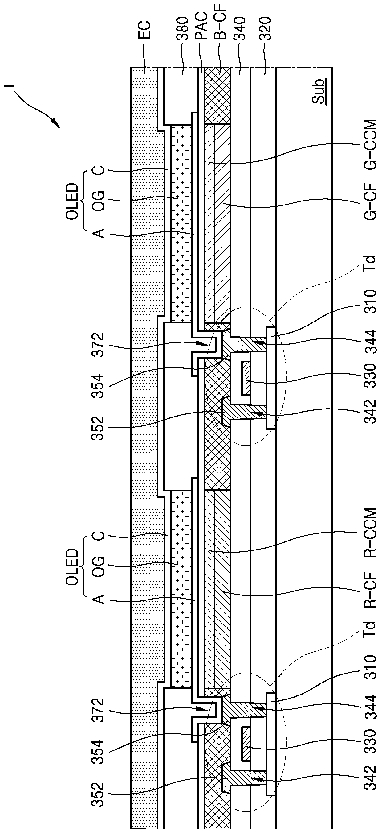
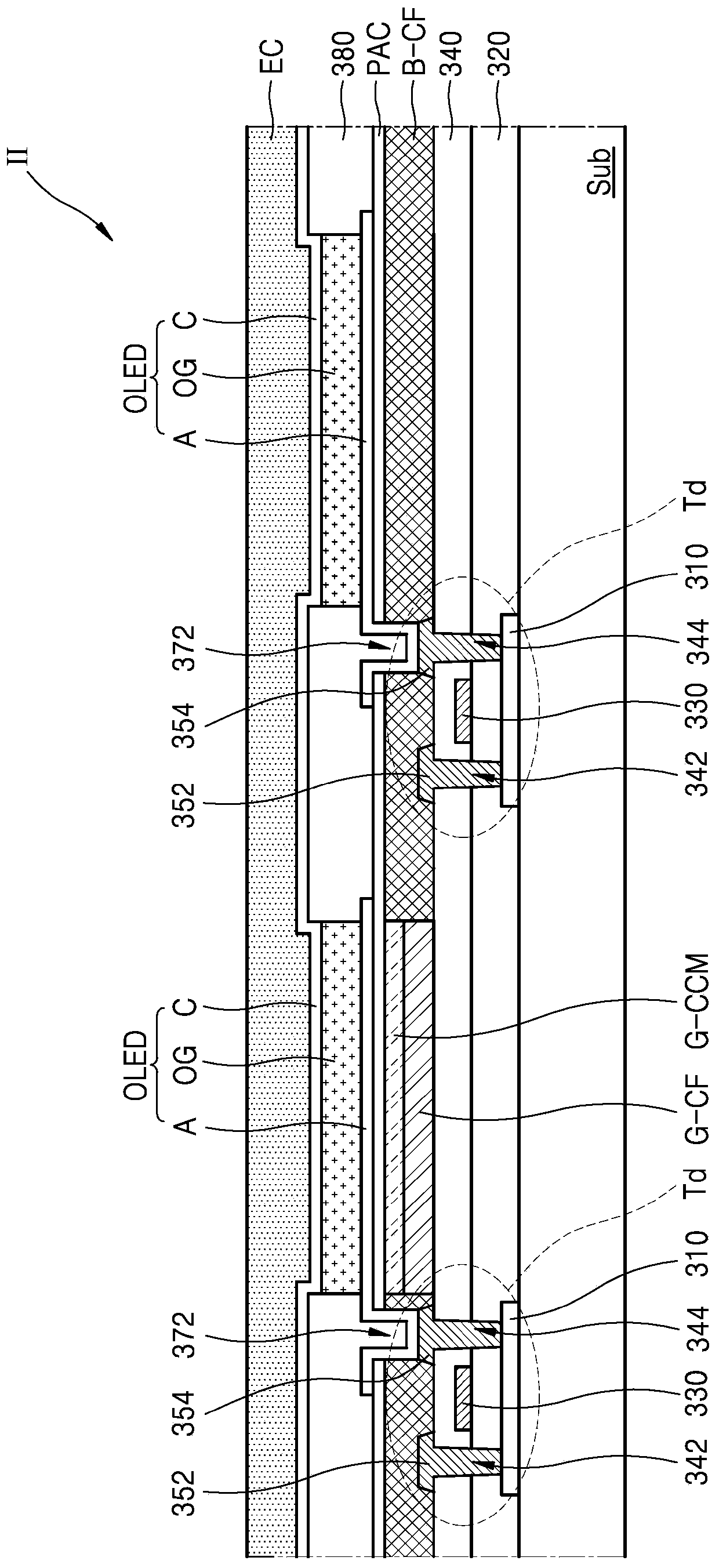
The invention discloses a self-light emitting display device. The self-light emitting display device comprises a circuit board including a driving thin-film transistor; a cathode; an organic film disposed between the circuit board and the cathode; an anode disposed between the circuit board and the organic film; and a color filter disposed between the circuit board and the anode and including a first color filter unit, a second color filter unit, and a third color filter unit; wherein the third color filter unit has a portion disposed between the first color filter unit and the second color filter unit, and wherein the third color filter unit is thicker than the first color filter unit and the second color filter unit.

Description

technical field [0001] The invention relates to a self-luminous display device. Background technique [0002] A self-luminous display device is a display device that emits light by itself. [0003] A display device is a device capable of visually displaying data. In the information society, various types of display devices capable of displaying images are increasingly required. Liquid crystal displays (LCDs) and organic light emitting diode display devices (OLEDs) have been widely used as display devices. [0004] Organic light emitting diode display devices display images using organic light emitting devices. [0005] Organic light emitting devices are self-emitting display devices that convert electrical energy into light energy using organic materials. Generally, an organic light emitting device has a structure in which an organic film is interposed between an anode and a cathode. When a driving voltage is supplied between the anode and the cathode, holes are injecte...

Claims


Application Information

Patent Timeline
Patent Type & Authority Applications(China)
IPC IPC(8): H01L27/32
CPCH10K59/35H10K59/38H10K59/12H10K50/865H10K2102/351H10K59/351H10K50/00H10K59/125H10K50/81H10K50/82
Inventor 李昇凡金垣来金水仁
Owner LG DISPLAY CO LTD
Learn More