

Rope descending device
A rope drop and rope groove technology, applied in life-saving equipment, building rescue, etc., can solve problems such as low efficiency and affecting normal use
- Summary
- Abstract
- Description
- Claims
- Application Information
AI Technical Summary
Problems solved by technology
Method used
Image

Examples
Embodiment 1
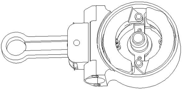
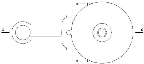
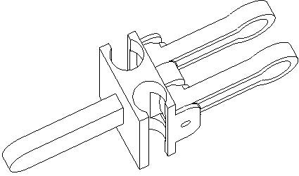
[0082] This embodiment provides a general-purpose speed limiter, which is composed of a turntable or a rotating arm [201], a centrifugal speed-limiting member [202], a speed-limiting shell [203], and a speed-guaranteed spring [204]. It mainly works on the principle of centrifugal force and friction self-locking. Its working principle is as follows: figure 1 shown. Speed-limiting shell [203] is fixed on the object that can provide speed-limiting torque. The rotating shaft [205] of the centrifugal speed-limiting member [202] is fixed on the rotating disk or the rotating arm [201]. The working speed-limiting direction of the centrifugal speed-limiting member [202] is the same as that of its free end, that is, when the rotation of the turntable or the rotating arm [201] is consistent with the direction of the free end of the centrifugal speed-limiting member [202], the centrifugal speed-limiting member [202] Provide working resistance, and the working resistance provided during ...
Embodiment 2
[0089]A rope descending device is composed of a fixed support, a safety rope, a safety belt, a safety belt connecting rope and a descender. It is characterized in that one end of the safety rope is tied to a fixed support, and the other end hangs down to the ground. The safety belt is tied on the person or the article to be lowered. The two ends of the safety belt connecting rope have self-locking hooks, one end is hung on the safety belt, and the other end is hung on the pull ring at the free end of the T-shaped hanging rod of the descender. The safety rope is stuck in the rope groove of the descender. The T-shaped hanging rod of the descender and the entire descending device rotate under the pulling force of the safety belt connecting rope. The T-shaped hanging rod directly presses the safety rope or presses the safety rope through the stopper plate, and the friction force generated when sliding down provides part of the descending resistance. At this moment, the total desc...
Embodiment 3
[0149] The rope descending device of the present embodiment is only made of fixed supports, safety ropes and descenders. The descender is the single-rope or double-rope automatic descender provided in the second embodiment. Both ends of the safety rope have anti-off self-locking hooks and hanging rings embedded in the safety rope. The self-locking hooks can be hung in the hanging rings to form a simple belt-type safety belt; or connect two safety ropes, A large rope loop is formed, and only a simple safety belt is reserved at one end, so that when a person slides down, the speed can be controlled by the safety rope rising on the other side. The safety rope is installed in the rope groove of the descender. The size of the self-locking hook is greater than the inner diameter of the rope groove of the descender, so that the safety rope cannot be pulled out from the rope groove of the descender. The pull ring of the T-shaped hanging rod of the descender is hung on the fixed supp...
PUM
 Abstract
Description
Claims
Application Information