
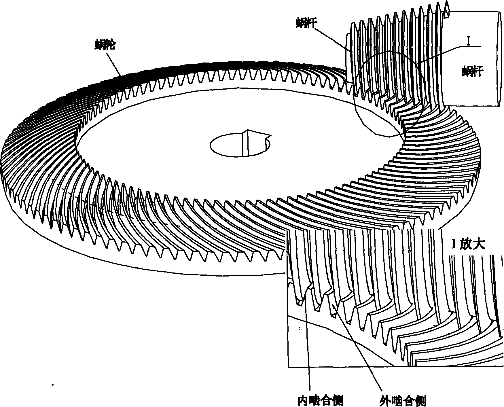
Machining method for dual-lead linear contact offset worm drive

A processing method and straight-line technology, applied in the direction of worm gears, elements with teeth, belts/chains/gears, etc., can solve the problems of difficult processing of tapered worm drives

Inactive Publication Date: 2011-08-17
JILIN UNIV
View PDF5 Cites 8 Cited by
  • Summary
  • Abstract
  • Description
  • Claims
  • Application Information

AI Technical Summary

Problems solved by technology

[0005] The purpose of the present invention is to solve the problem of difficult processing of bevel worm transmission, on the basis of a simple and accurate design and calculation method, propose a method that can use existing machine tools and cutting tools to cut and process the tooth surface of worm gear without adding Equipment or processing methods using special-purpose machine tools and special-purpose tools

Method used


Image

  • Machining method for dual-lead linear contact offset worm drive
  • Machining method for dual-lead linear contact offset worm drive
  • Machining method for dual-lead linear contact offset worm drive

Examples


Embodiment Construction

[0348] 1. Design example of conical worm and worm gear transmission

[0349] A. Cylindrical worm drive design example:

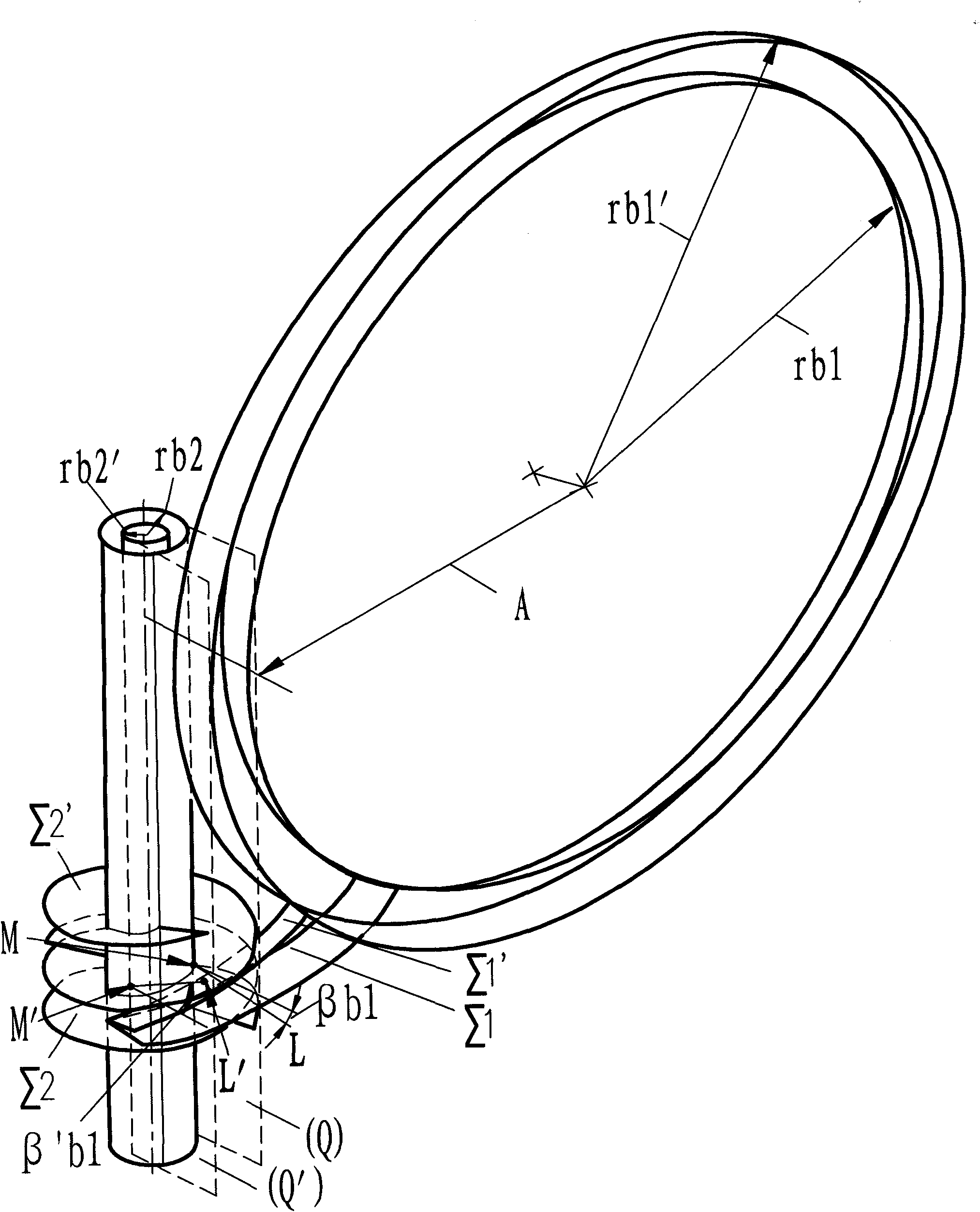
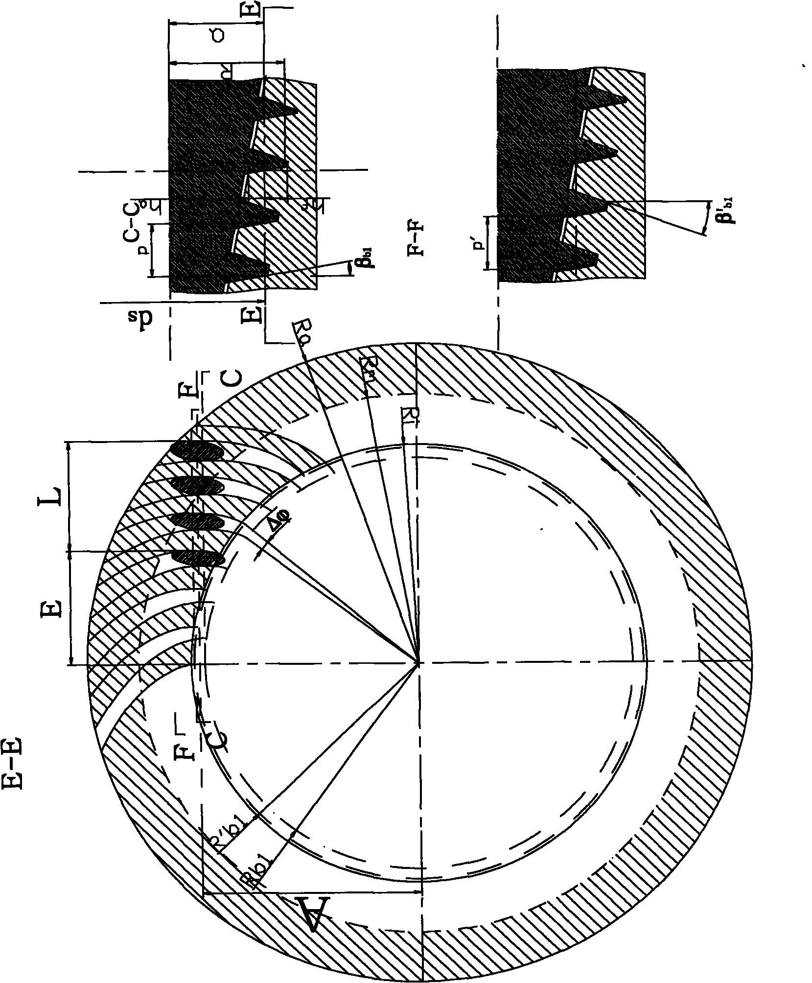
[0350] It is known that the center distance A=100, the transmission ratio i12 and the number of teeth z, z=55. Roughly calculate the outer diameter of the worm d, d=kA=2R, d=54; selected helix angle β b1 , β′ b1 , β b1 = 20°, β' b1 =30°, calculate base cylinder radius, R b2 = 4.758, R b1 =95.242, R' b2 = 3.251, R' b1 =103.251; take n=10%z=5

[0351] 1) Preliminary calculation of the outer diameter R of the worm gear a , take R a =152

[0352] 2) Calculate the radius R of the worm gear index circle m , R m ≈109.1

[0353] 3) According to R m Calculate the modulus m, m = 2 R m z = 3.967

[0354] 4) Calculate the worm gear tooth height

[0355] Addendum height t′ at the pitch circle m and dedendum height t′ m ,...


PUM


Abstract

The invention discloses a machining method for dual-lead linear contact offset worm drive, which belongs to the technical field of manufacture. The dual-lead linear contact offset worm drive belongs to a spiroid drive form in worm wheel and worm drive. The machining method disclosed by the invention comprises a milling machining method, a fly-cutter hobbing machining method and a numerical control lathe machining method. By using the invention, accurate and structure-simplified worm wheel and worm are obtained aiming at a dual-lead linear contact offset worm drive designing method without efficient and high-precision machining of a special lathe, and a tooth surface is accurately machined by using the traditional lathe and the traditional tool without addition of other equipment or use ofa special lathe and a special tool.

Description

[0001] divisional application [0002] The present invention is a divisional application titled "Double-Lead Linear Contact Offset Worm Drive Design and Manufacturing Method", original application date: May 27, 2009, application number: 200910067019.7. technical field [0003] The invention belongs to the field of mechanical principles and mechanical manufacturing, and relates to gear meshing theory and worm drive. Background technique [0004] Since the 1950s, conical worm transmissions have appeared. This transmission form has improved the efficiency and load capacity of worm transmissions, increased the transmission ratio, and can replace copper with steel for worm gear materials. But about this transmission There are not many studies and applications of the worm gear, the main reason is that the meshing principle is complex, and the mathematical relationship used to describe the principle and the tooth surface is also very complicated, which makes the design and manufact...

Claims


Application Information

Patent Timeline
Patent Type & Authority Applications(China)
IPC IPC(8): B23F11/00
Inventor 张学成聂建辉
Owner JILIN UNIV
Learn More