Bubbling device for molten glass

A bubbling device and glass melting technology, applied in glass furnace equipment, glass manufacturing equipment, manufacturing tools, etc., can solve problems such as inability to adjust, difficult to adjust, and system scrapping, so as to increase system reliability, safety, and cost Reduced effect

Inactive Publication Date: 2011-08-17
QINHUANGDAO KAIWEI SCI & TECH +1
View PDF3 Cites 11 Cited by
  • Summary
  • Abstract
  • Description
  • Claims
  • Application Information

AI Technical Summary

Problems solved by technology

Bubble tubes are subject to chemical corrosion and physical wear by glass liquid or gas outlet blockage at high temperatures, making it difficult or impossible to replace them. A problem with one of the bubbler devices causes the system to be scrapped; the second is the convection of the glass liquid around the bubble tubes. After strengthening, the temperature of the molten glass at the bottom of the kiln increases, which inten

Method used


Image

  • Bubbling device for molten glass
  • Bubbling device for molten glass
  • Bubbling device for molten glass

Examples


Embodiment Construction

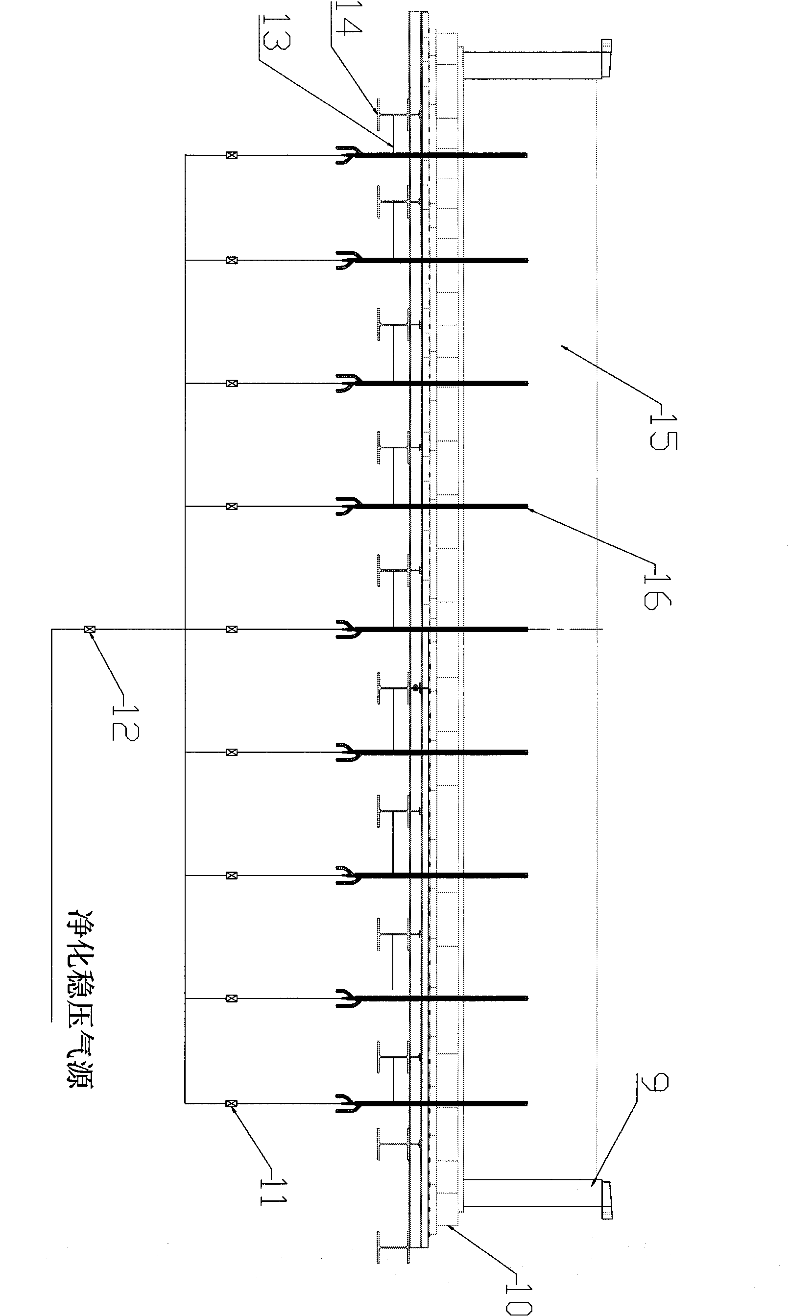
[0019] A glass tank furnace with a daily melting capacity of 400 tons, the cross section is as follows figure 2 Shown, the pool wall (9) and the bottom of the pool (10) form a rectangular pool kiln, and the glass liquid (15) is filled with it, and the width of the pool kiln is 10.3m, and the glass liquid depth is 1.15m. Nine water-cooled porous bubbling devices (16) are arranged, and each bubbling device is connected and fixed to the steel structure (14) at the bottom of the pool through a fixer (13). Loosen the retainer (13) when it is necessary to adjust the depth of the bubbling device in the glass liquid or change it, and keep it fastened in the normal state.

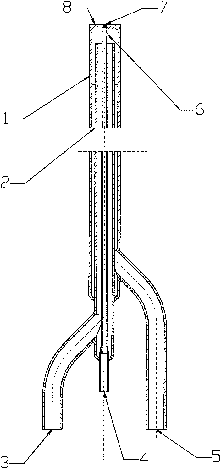
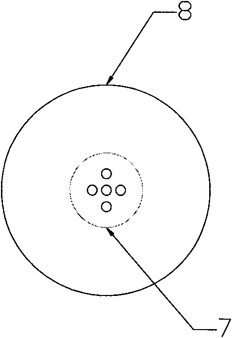
[0020] Water-cooled porous bubbling device such as figure 1 As shown, the cooling pipeline is composed of outer pipe (1), inner pipe (2), water inlet pipe (3) and water outlet pipe (5); the material is heat-resistant stainless steel; the outer diameter of the outer pipe (1) is 42mm, and the inner pipe (2 ), water...


PUM


Abstract

The invention discloses a porous bubbling device with a cooling structure, and belongs to the field of tank furnace melting for glass production. The bubbling device consists of a porous gas pipeline and a cooling pipeline for protecting the gas pipeline; the bubbling device can be positioned at any position in the depth direction of molten glass by cooling and can be adjusted according to different produced glass; and the cross section area of a single gas pipe outlet of a bubbling port (7) can be reduced through multiple pores, and the purposes of preventing the molten glass from flowing backward and controlling bubble frequency and bubble diameter are fulfilled by combining a one-way valve (or check valve) and a pressure adjusting valve of an upstream air supply pipeline of an air inlet (4).

Description

technical field [0001] The invention is a porous bubbling device with a cooling mode, which belongs to the field of glass production tank furnace melting. Background technique [0002] Glass tank kiln bubbling technology is a new forced melting technology that appeared in the 1950s. After more than half a century of development and continuous improvement, it has become one of the indispensable forced melting technical measures for modern glass tank kilns. [0003] Inside the glass tank furnace, the radiant heat of the flame is transferred to the batch material and the molten glass, and the flow of the molten glass in the melting tank is the basic principle of melting and homogenization of the tank furnace. All the technical measures of forced melting and improving the quality of molten glass are carried out to obtain the maximum heat with batch materials, increase the temperature of molten glass, strengthen the flow of molten glass and make the thermal convection of molten g...

Claims


Application Information

Patent Timeline
IPC IPC(8): C03B5/193
CPCC03B5/193
Inventor 肖凯生胡玉良郑浩东王鉴张小良包金金刘国刚
Owner QINHUANGDAO KAIWEI SCI & TECH
Why Eureka
Try Eureka