Fish-shaped steel tube pile

A steel pipe pile, fish-shaped technology, applied in sheet pile walls, buildings, foundation structure engineering, etc., can solve the problem of low torsional load capacity, and achieve the effect of strong torsional resistance, good stability, and control of horizontal deformation

Inactive Publication Date: 2011-08-17
ZHEJIANG UNIV
View PDF4 Cites 7 Cited by
  • Summary
  • Abstract
  • Description
  • Claims
  • Application Information

AI Technical Summary

Problems solved by technology

[0004] In view of the low torsional load bearing capacity of steel pipe pile foundations widely used in offshore engineering and port engineering

Method used


Image

  • Fish-shaped steel tube pile
  • Fish-shaped steel tube pile
  • Fish-shaped steel tube pile

Examples


Embodiment 1

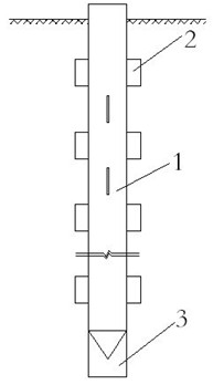
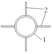
[0031] Such as figure 1 , image 3 As shown, the present invention welds multi-layer side fins 3 sequentially from top to bottom on the side of the steel pipe pile 1 closed at the bottom, and each layer of side fins 3 has 2 to 4 pieces; the tail fin is welded on the side of the tapered tip of the steel pipe pile closed at the bottom slice 3.

[0032] Such as Figure 4 As shown, the side wings are rectangular (a), inverted right triangle (b), inverted trapezoid (c), combination of rectangle and inverted trapezoid (d) or combination of rectangle and sector (e) .

[0033] Such as Figure 5 Shown is the front view (a) and side view (b) of an optional shape diagram of the tail fin of the closed steel pipe pile, the bottom end of the tail fin is a straight line; as Figure 6 Shown are the front view (a) and the side view (b) of another alternative shape diagram of the tail fin of a closed-end steel pipe pile, where the bottom end of the tail fin is the tip.

[0034] Each laye...

Embodiment 2

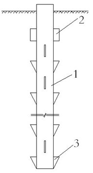
[0037] Such as figure 2 , image 3 As shown, the side of the steel pipe pile 1 with the bottom opening is welded in sequence from top to bottom with multiple layers of side fins 2, and each layer of side fins is 2 to 4; There are 2 to 4 tail fins.

[0038] Such as Figure 4 As shown, the side fins and tail fins are rectangular (a), inverted right triangle (b), inverted trapezoid (c), combination of rectangle and inverted trapezoid (d) or combination of rectangle and sector (e).

[0039] Each layer of the multi-layer side wings can be arranged in a staggered equidistant or staggered unequal distance, figure 2 In the middle, there are two symmetrical arrangements of side wings on each layer, and the side wings between the two layers are arranged staggered and equidistant. The side wings welded on the side of the steel pipe pile can be a combination of the same or different side wings.

[0040] Whether the tail fins are set or not is determined according to actual needs. ...


PUM


Abstract

The invention discloses a fish-shaped steel tube pile which has two modes: one mode is that the side surface of a steel tube pile with a sealed bottom is welded with a plurality of layers of side wing slices from up to down in sequence, the number of the wing slices of each layer is 2-4, and the side surface of a conical tip end of the steel tube pile with the sealed bottom is welded with a tail wing slice; and the other mode is that the side surface of the steel tube pile with an open bottom is welded with a plurality of layers of side wing slices from up to down in sequence, the number of the wing slices of each layer is 2-4, and the side surface of the lower end of the steel tube pile with the open bottom is welded with a layer of tail wing slices, and the number of the tail wing slices is 2-4. In the fish-shaped steel tube pile, when a single pile is applied with torque action, a pile body and the wing slices at a pile end extrude an earth body to generate greater earth body counterforce, so that the torque bearing force of the single pile can be greatly improved. The fish-shaped steel tube pile improves the stressed characteristics of the traditional circular steel tube pile under the torque action, has strong twisting resistance capability, good stability and low refomation cost, can be used in the foundations of various structures in coastal engineering and port engineering.

Description

technical field [0001] The invention relates to steel pipe piles, in particular to a fish-shaped steel pipe pile. Background technique [0002] Axial, horizontal and torsional are the three basic load modes of pile foundations. In order to improve the vertical and horizontal bearing capacity of single piles, various pile foundation forms have been proposed, but the technical measures and pile foundation forms aimed at improving the torsional capacity of single piles are still very limited. [0003] Circular cross-section piles are currently the most commonly used pile cross-sectional shape. Round steel pipe piles are generally used in offshore projects and port projects, and offshore construction operations can be quickly completed by using large-scale piling equipment. The torsional capacity of ordinary circular section piles mainly comes from the frictional resistance between piles and soil. Due to the limited tangential frictional resistance provided by the pile-soil in...

Claims


Application Information

Patent Timeline
IPC IPC(8): E02D5/28E02D5/72
Inventor 孔令刚袁廉华陈云敏王顺玉陈仁朋樊继营
Owner ZHEJIANG UNIV
Why Eureka
Try Eureka