Tunnel curve segment lofting method based on circle coordinates

A technology of curve segment and circular coordinates, applied in the field of tunnel curve segment stakeout based on circle coordinates, can solve the problems of low stakeout accuracy, large amount of calculation, and many stakeout steps, and achieves less error-prone, less computation, and high stakeout accuracy. Effect

Inactive Publication Date: 2011-08-17
龚晓斌 +3
View PDF7 Cites 15 Cited by
  • Summary
  • Abstract
  • Description
  • Claims
  • Application Information

AI Technical Summary

Problems solved by technology

[0003] Traditional curve segment stakeout mainly includes deflection angle method and tangent support distance method, etc. Due to the disadvantages of these methods, such as large amount of calculation and many stakeout steps, and because of the different methods mastered by surveyors, there are often different stakeout methods used in the same tunnel curve segment. The different methods lead to the staggering of the inner and outer arc side walls of the tunnel curve section, resulting in poor shape of the c

Method used


Image

  • Tunnel curve segment lofting method based on circle coordinates
  • Tunnel curve segment lofting method based on circle coordinates
  • Tunnel curve segment lofting method based on circle coordinates

Examples


Example Embodiment

[0040] Example 1:

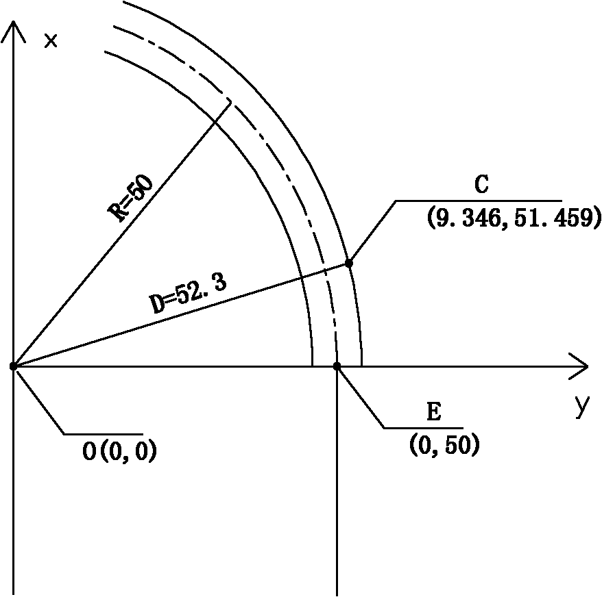
[0041] Center circle coordinate method, referred to as circle center coordinate method.

[0042] The basic steps of stakeout are:

[0043] The first step: set up a total station on the stake points with known coordinates in the tunnel, and require the total station to be able to observe the section of the curve section. Swiss Leica total station. The so-called total station is to put the line once without moving the instrument, and it can be completed in one station, unlike the theodolite, which needs to be adjusted many times and set up a prism at the measuring point; the prism is an auxiliary device of the total station, which is essentially a reflector. When installing it on a prism rod, put it on the point to be measured, the total station aims at it and shoots a beam of laser light, and the laser beam is reflected back through the prism, and the total station can get the coordinates of that point ;According to the data provided by the drawing or con...

Example Embodiment

[0060] Example 2:

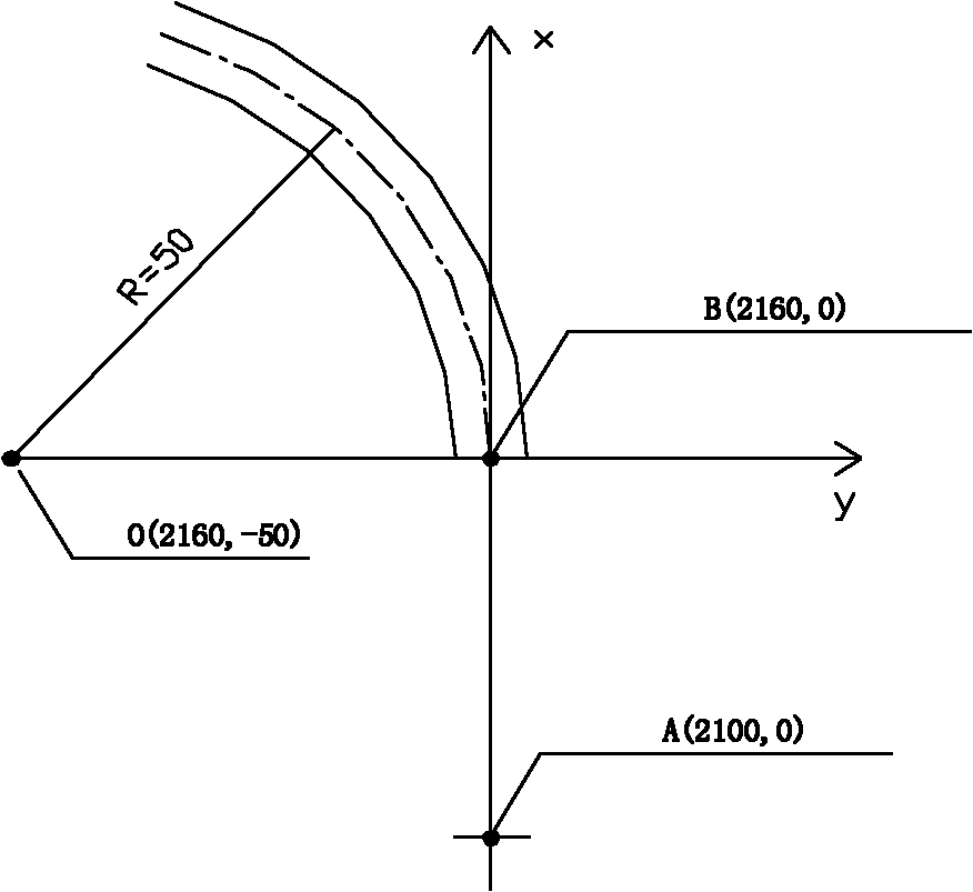
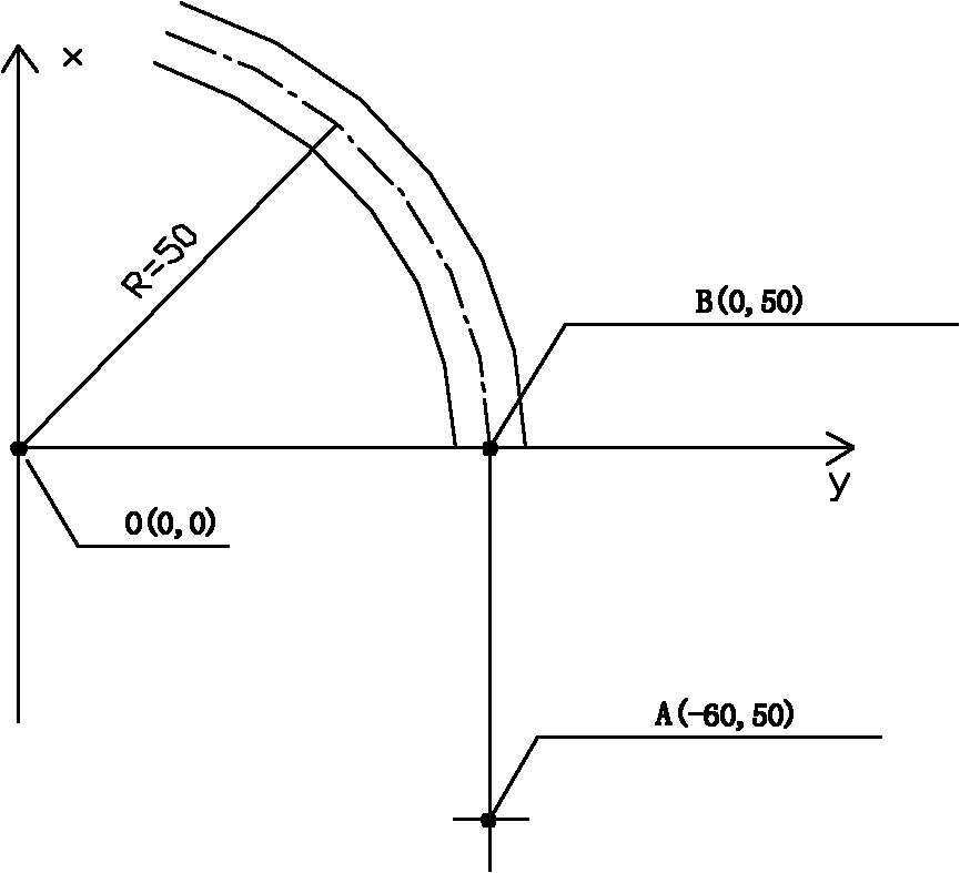
[0061] Tangent circle coordinate method, referred to as tangent point coordinate method.

[0062] The stakeout method and steps of the tangent coordinate method are basically the same as the circle center coordinate method, the only difference is that the coordinate origin is the tangent point, and the circular coordinate method formula x 2 +y 2 = r 2 Then it can be evolved into the calculation formula r of the tangent point coordinate method 2 =x 2 +(r-|y|) 2 (Schematic diagram of the measurement coordinate system of the tangent coordinate method is shown in Figure 4 ) or use the formula (x-a) 2 +(y-b) 2 = r 2 , where (a, b) is the coordinates of the center of the circle.

[0063] In the tangent point coordinate method, after the drawing coordinate system and the measurement coordinate system are converted, the measured coordinates are relative to the tangent point coordinates, and the position of the measured point relative to the center of the ...


PUM


Abstract

The invention discloses a tunnel curve segment lofting method based on circle coordinates, which is characterized in that the method comprises the following steps of: step 1. preparation step: determining the positions of an original point of a measuring-coordinate system and a circle center O (a, b) of a tunnel curve segment, and establishing the measuring-coordinate system, namely, an XOY coordinate system; step 2: lofting step: obtaining coordinates (x, y) of a measuring point at a cross section, calculating the value of (x-a)2+(y-b)2-r2, namely, a calculated value, wherein r represents the radius of the tunnel curve segment; moving the position of the measuring point according to the size and the plus-minus of the calculated value, updating the coordinates (x, y) of the measuring point till determining points of intersections of the cross section with an axis, an inner arc and an outer arc, thus finishing the lofting of the cross section; step 3. in the tunneling process of the tunnel curve segment, repeating the step 2, and finishing the lofting of the whole tunnel curve segment. The tunnel curve segment lofting method based on the circle coordinates has less calculated amount, is easy to implement and has high lofting precision.

Description

technical field [0001] The invention belongs to the field of underground engineering construction and relates to a circular coordinate-based method for setting out tunnel curve sections. Background technique [0002] In engineering construction, setting out the tunnel curve section is not only the key and difficult point of the survey work, but also an important link that affects the tunnel penetration accuracy and ensures the quality of the project. The content of tunnel curve stakeout is basically the same as that of off-site curve stakeout. In addition to measuring the obvious feature points such as the straight circle point, the middle point of the curve, and the straight circle point of the curve, it is also necessary to measure the curve every certain distance (2m, 3m or any m) Measure the auxiliary points on the circular curve, and then connect these auxiliary points with a smooth curve, so that the shape and position of the curve can be accurately set out on the grou...

Claims


Application Information

Patent Timeline
IPC IPC(8): E21D9/00
Inventor 龚晓斌宋仲华黄增强罗会军
Owner 龚晓斌
Why Eureka
Try Eureka