
Welding seam measuring method based on micro field depth

A measurement method and local technology, applied in the direction of measuring devices, instruments, optical devices, etc., can solve the problem of not being able to stably and reliably extract the center position of the weld seam and the width of the seam gap, the detection failure of the seam center and width, Geometric features cannot be fully represented, etc.

Inactive Publication Date: 2011-08-17
HUAZHONG UNIV OF SCI & TECH +1
View PDF5 Cites 13 Cited by
  • Summary
  • Abstract
  • Description
  • Claims
  • Application Information

AI Technical Summary

Problems solved by technology

[0007] To sum up, there are currently many researches and related products on visual sensors for weld seam measurement, but most of the above-mentioned visual sensors are aimed at argon arc welding of arc welding robots, and the seam width is wider (generally greater than 0.5mm), and the joints are mostly V-shaped
However, laser welding seams are mostly butt joints, and the width of the seam is narrow (for a 2mm thin plate, the width of the seam is required to be less than 0.1mm). However, most of the current visual weld inspection technologies are based on triangulation of line structured light. According to the principle of measurement, for the butt seam with a small weld, due to the limitation of the structured light triangulation principle or the lateral resolution of the sensor (because its optical magnification is less than 1, the geometric features of the narrow seam cannot be fully displayed in the image performance, resulting in the failure of seam center and width detection), the currently used laser vision sensor cannot extract the center position of the weld seam and the width of the seam gap stably and reliably

Method used


Image

  • Welding seam measuring method based on micro field depth
  • Welding seam measuring method based on micro field depth
  • Welding seam measuring method based on micro field depth

Examples


Embodiment Construction

[0026] First introduce the related concepts:

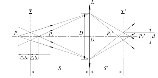
[0027] After the camera is focused, it can form a clear image in the range before and after the focus. This range is called the depth of field. For general household cameras, the larger the depth of field, the better. For example, for a lens with a focal length of 35mm, when the shooting distance is about 3m, the depth of field is about 0.21m, and if the shooting distance is 10m, the depth of field is infinite. When the shooting distance is 50mm, the depth of field is about 3mm; when the shooting distance is 15mm, the depth of field is about 0.017mm, and the optical magnification at this time is 2 times. In general, the greater the optical magnification, the smaller the depth of field. Therefore, in the present invention, the depth of field formed when the optical magnification is greater than 2 times is called a micro depth of field. Compared with the lens, the micro depth of field is located in a specific space area in front ...


PUM


Abstract

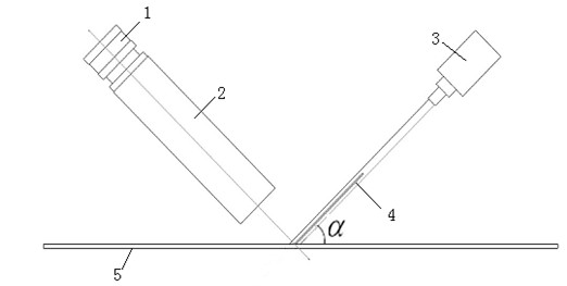
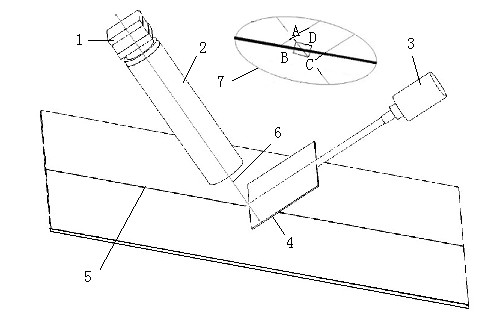
The invention discloses a welding seam measuring method based on micro field depth, comprising the following steps: placing a camera with optical amplification factor being more than 2 slantwise relative to the local surface of a welding seam, shooting the local surface of the welding seam twice under the condition of different distance between camera and the local surface of the welding seam, extracting clear bands from two shot images, respectively obtaining the coordinate of each object point which corresponds to each image point on the centre lines of two clear bands in a direction perpendicular to the welding seam to obtain two straight line segments in a world coordinate, carrying out plane fitting by using the two straight line segments to obtain the normal vector value of the local surface of the welding seam, and extracting the boundary of the local surface of the welding seam from any one of the clear bands to obtain the width and the center coordinate of the local surface of the welding seam. The welding seam measuring method can be used to stably and reliably measure the center coordinate, the width and the normal vector value of the local surface of the complex micro-fine welding seam, is easy to operate and has high detection precision.

Description

technical field [0001] The invention belongs to the field of visual measurement technology and laser welding processing technology, and in particular relates to a welding seam measurement method capable of measuring the seam center coordinates, width and local surface normal vector of complex narrow and fine seams. Background technique [0002] Laser welding has the advantages of high energy density, fast welding speed, small heat-affected zone range, small welding thermal deformation, large depth-to-width ratio of the weld, and easy automatic control. With the successful development of high-power lasers and the development of laser fiber transmission technology Perfect, laser welding technology is gradually widely used in the automotive industry, shipbuilding, aerospace industry and other fields. [0003] In laser welding, the focused spot diameter of the welding laser beam is very small, about 0.3mm, so the laser welding process has extremely high requirements on the assem...

Claims


Application Information

Patent Timeline
IPC IPC(8): G01B11/14
Inventor 王平江袁丹辉黄雅婷齐江飞徐长杰彭芳瑜李斌唐小琦陈吉红
Owner HUAZHONG UNIV OF SCI & TECH
Learn More