Framework crack monitoring method and monitoring devices thereof

A crack and framing technology, used in measuring devices, machine/structural component testing, vibration testing, etc., can solve problems such as detection accuracy limitation, strain gage resistance increase, and current increase, and achieve high accuracy and quantity. The effect of few, continuous inspections

Active Publication Date: 2011-08-17
TANGZHI SCI & TECH HUNAN DEV CO LTD
View PDF8 Cites 14 Cited by
  • Summary
  • Abstract
  • Description
  • Claims
  • Application Information

AI Technical Summary

Problems solved by technology

[0004] The principle of magnetic flaw detection is: sprinkle iron powder on the surface of the machine made of steel, use the magnetic poles (such as N and S poles) of strong electromagnets to straddle the two sides of possible cracks, and use the cracks to cut off the magnetic field lines of the magnets. The magnetic circuit formed by the iron and steel machine material makes the magnetic force line diverge to the surface of the machine, and attracts the iron powder to the crack to form a natural law and phenomenon to supplement the magnetic circuit. Through the iron powder gathering place that can be seen by the human eye, the implicit Cracks; this technology is not suitable for machines made of non-ferromagnetic materials, such as aluminum alloy machines, or machines made of weak magnetic materials (such as various stainless steels). Unable to effectively, quickly and accurately identify hidden dangers
[0005] The principle of eddy current flaw detection is: apply high-frequency current to the planar inductance coil, the coil generates alternating magnetic force lines, move the coil along the surface of the machine, the magnetic force lines are coupled into the metal material of the machine, and eddy current is generated in the metal material material, then the current of the coil increases. Large; if there is a crack in the shallow layer of the material where the coil moves, the eddy current in the material decreases, and the current in the coil also decreases, and the crack is identified by the current decrease; the disadvantage of this technology is that it cannot identify deeper cracks, and is also subject to Whether the surface of the machine is flat, smooth and whether the manual operation is appropriate
[0006] The principle of ultrasonic flaw detection is to use an ultrasonic sounding probe close to the surface of the machine, and radiate short-term ultrasonic waves into the machine through a coupling agent, or use an ultrasonic receiving probe to detect ultrasonic waves at other positions of the machine, and identify them by finding that the ultrasonic transmission ability becomes smaller There may be cracks in the machine between the transmitting and receiving probes; or through the receiving probe combined with the transmitting probe, the received echo of the transmitted wave arrives earlier than other parts when the transmission is stopped and the front is found Possible cracks; this method requires smooth surface of the machine to facilitate the coupling of transmitting and receiving probes, and is also troubled by small cracks and cracks at close distances that are not easy to find and identify
[0007] The principle of coloring inspection is: clean the surface of the machine that may have surface cracks, apply a dark penetrant, which has a strong ability to flow along the metal surface (especially cracks), and then wipe off the machine. Apply white paint to the penetrating liquid on the surface. If there is a crack in a certain place that has infiltrated the penetrating liquid before, the penetrating liquid will flow out to the white paint layer in reverse and stain it. It can be identified by the staining position and distribution shape on the white paint Existence and distribution of cracks; this technology can only identify cracks that penetrate the surface, and can only be used to verify suspected cracks, which is not convenient for common and frequent use
[0008] The principle of dynamic stress monitoring with strain gauges all over the place is to paste a large number of strain gauges on the surface of the machine where cracks are expected to occur. When the machine is moving, if the crack covered by a certain strain gauge opens, the resistance material of the strain gauge will It is stretched and elongated, and the possible cracks are identified by detecting the small increase in resistance compared to other strain gauges; the number of strain gauges required for this technology is huge, and the position of the sticking must be estimated very accurately , otherwise it is invalid; also because there will be stretching or compression in the elastic range without cracks on the surface of the machine during vibration or work, which will also cause the resistance increase of the strain gauge, so its detection accuracy is limited
[0009] Therefore, many existing crack detection technologies have deficiencies in monitoring frequency, implementation difficulty, cost level, restrictions on the detected object (such as stopping use), and the number of sensors used. A new method that saves the number of sensors, is suitable for harsh operating environments, and can be accurately and frequently monitored at any time during online operation to make up for the above shortcomings

Method used


Image

  • Framework crack monitoring method and monitoring devices thereof
  • Framework crack monitoring method and monitoring devices thereof
  • Framework crack monitoring method and monitoring devices thereof

Examples


Embodiment 1

[0059] Embodiment 1, vehicle frame crack online diagnosis system

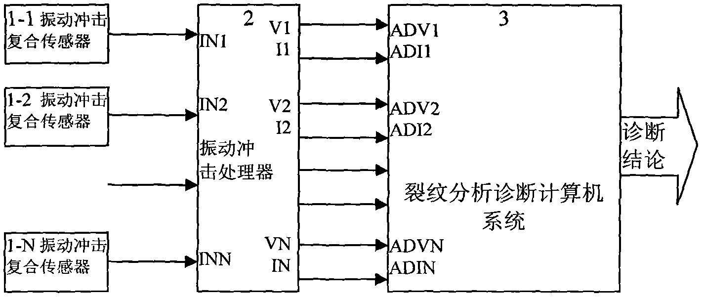
[0060] An on-line diagnosis system for vehicle frame cracks constructed according to the frame crack monitoring method and its monitoring device, which includes multiple vibration and shock composite sensors (1-1 to 1-4) installed on the vehicle bogie, and monitors the multiple sensors A vibration shock processor 2 that separates the vibration shock signal into a vibration signal and a shock resonance demodulation signal, and a crack analysis and diagnosis computer that synchronously samples the vibration shock signal output by the vibration shock processor and includes crack identification and diagnosis software built according to the monitoring method The vehicle frame crack monitoring device composed of system 3, as attached figure 1The method is characterized in that the crack analysis and diagnosis computer system 3 contains crack analysis and diagnosis software supported by the vehicle frame crack monito...


PUM


Abstract

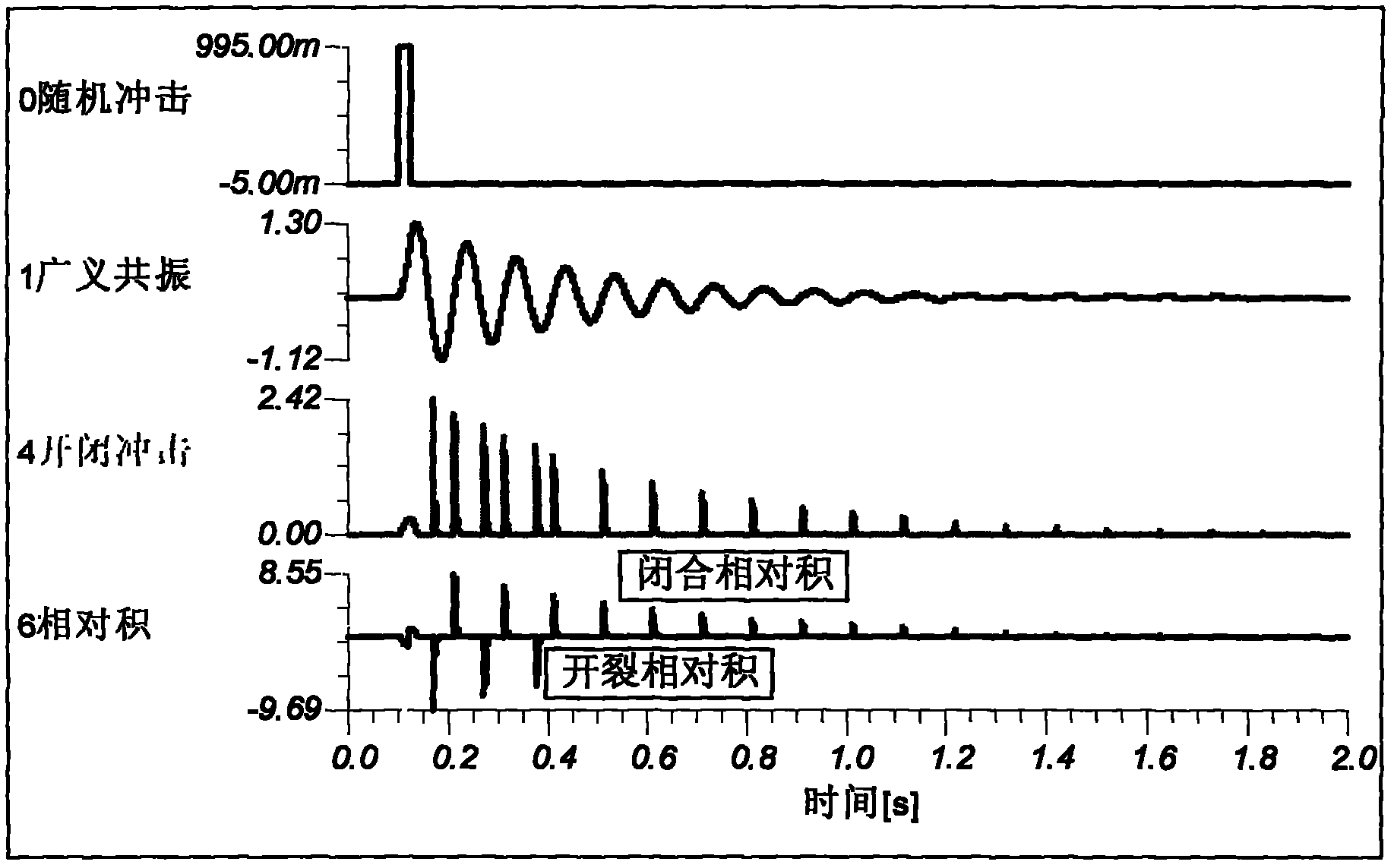
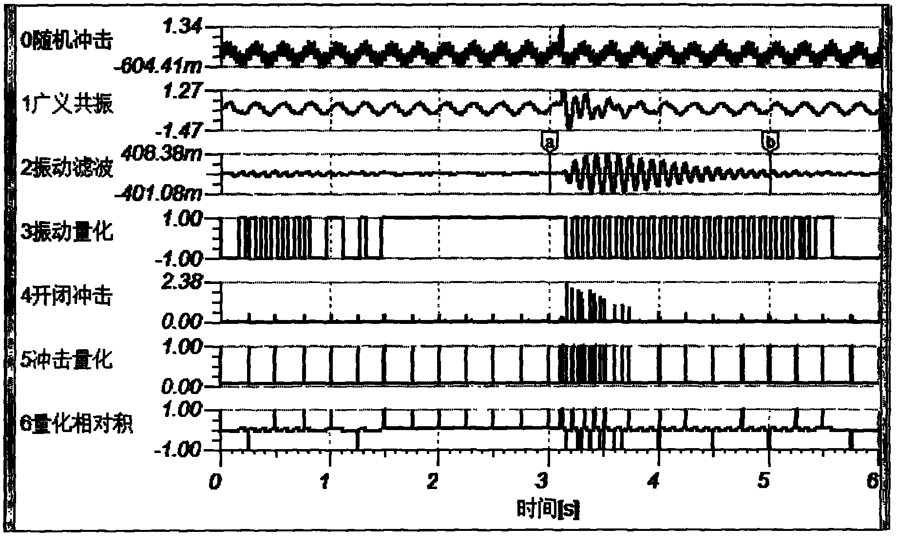
The invention discloses a framework crack monitoring method and monitoring devices thereof, mainly used for realizing the fault diagnosis seriously endangering safety, such as framework cracks and the like, through detecting the generalized resonance of a framework which is aroused by random impact and crack starting and closing impact caused by the generalized resonance during the running process of a vehicle and identifying the corresponding relation between the generalized resonance and the crack starting and closing impact. The method comprises the following steps of: performing modal analysis on the framework; further selecting the monitoring point of a vibration impact compound sensor which is used for monitoring the framework; using the generalized resonance of the framework modal, which is aroused by external random impact obtained at the monitoring point, and the generalized resonance impact aroused by the generalized resonance to judge a relative product used for crack identification; carrying out narrow-band filtering, relative product quantifying and the confidence calculation and the like on the modal frequency of the generalized resonance obtained at the monitoring point to judge crack early warning. The invention also provides monitoring devices applying any one of the framework crack monitoring methods and the monitoring devices include a compound sensor, a vibration impact processor and a crack analysis diagnosis computer system.

Description

technical field [0001] The invention relates to a frame crack monitoring method and a monitoring device thereof, which are mainly used for detecting the generalized resonance excited by the random impact of the frame and the opening and closing impact of the crack caused by the generalized resonance during the driving process of the vehicle, and identifying its cracks. The relative relationship can realize the fault diagnosis of structural cracks and other serious threats to safety. Background technique [0002] The vehicle frame is the main supporting component between the carriage carrying passengers and goods and the wheels. Due to the harsh working conditions, cracks and fractures are almost inevitable, causing serious accidents. Therefore, it is necessary to identify cracks before they develop into fractures, and repair them in time to prevent accidents caused by fault expansion. [0003] The existing monitoring methods for vehicle frame cracks mainly rely on maintenan...

Claims


Application Information

Patent Timeline
Patent Type & Authority Applications(China)
IPC IPC(8): G01M17/08G01M7/02
Inventor 唐德尧黄贵发王智陈湘
Owner TANGZHI SCI & TECH HUNAN DEV CO LTD
Why Eureka
Try Eureka