Impact loading mechanism

A loading mechanism and loading arm technology, applied in the direction of using repetitive force/pulsation force to test the strength of materials, etc., can solve the problem of difficulty in producing effects, and achieve the effect of less hysteresis, less elastic deformation, and ensuring neutrality

Inactive Publication Date: 2011-08-17
BEIHANG UNIV
View PDF3 Cites 17 Cited by
  • Summary
  • Abstract
  • Description
  • Claims
  • Application Information

AI Technical Summary

Problems solved by technology

Such a loading method is generally difficult to control to obtain the expected design results, and the impact often has a high frequency, which is difficult to produce good results in some places that need to simulate low-frequency impact

Method used


Image

  • Impact loading mechanism
  • Impact loading mechanism
  • Impact loading mechanism

Examples


Embodiment Construction

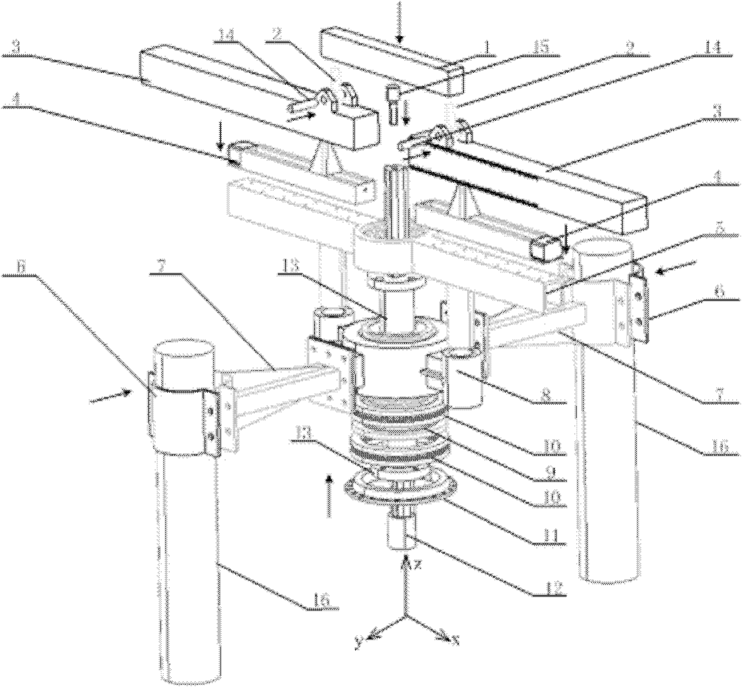
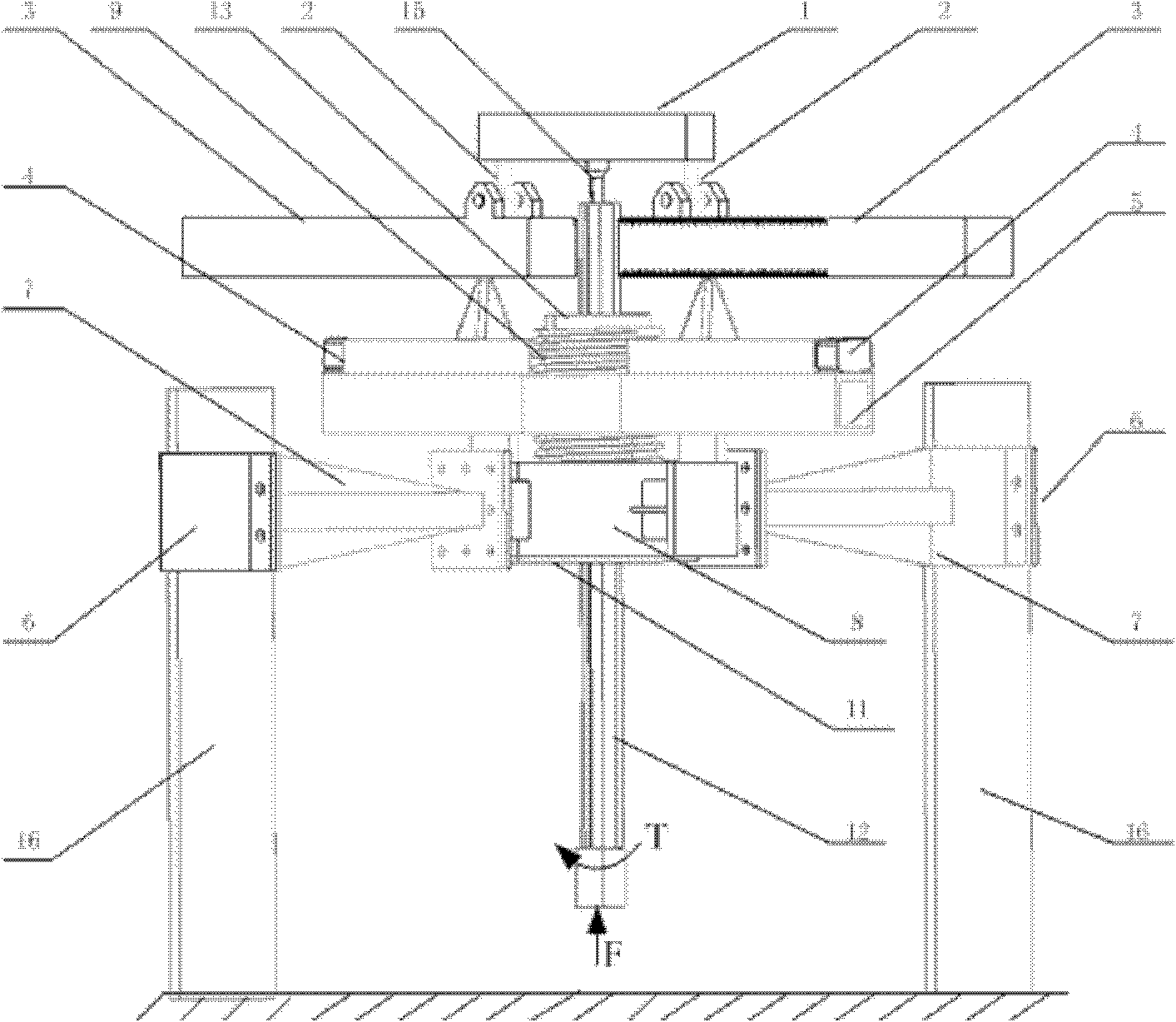
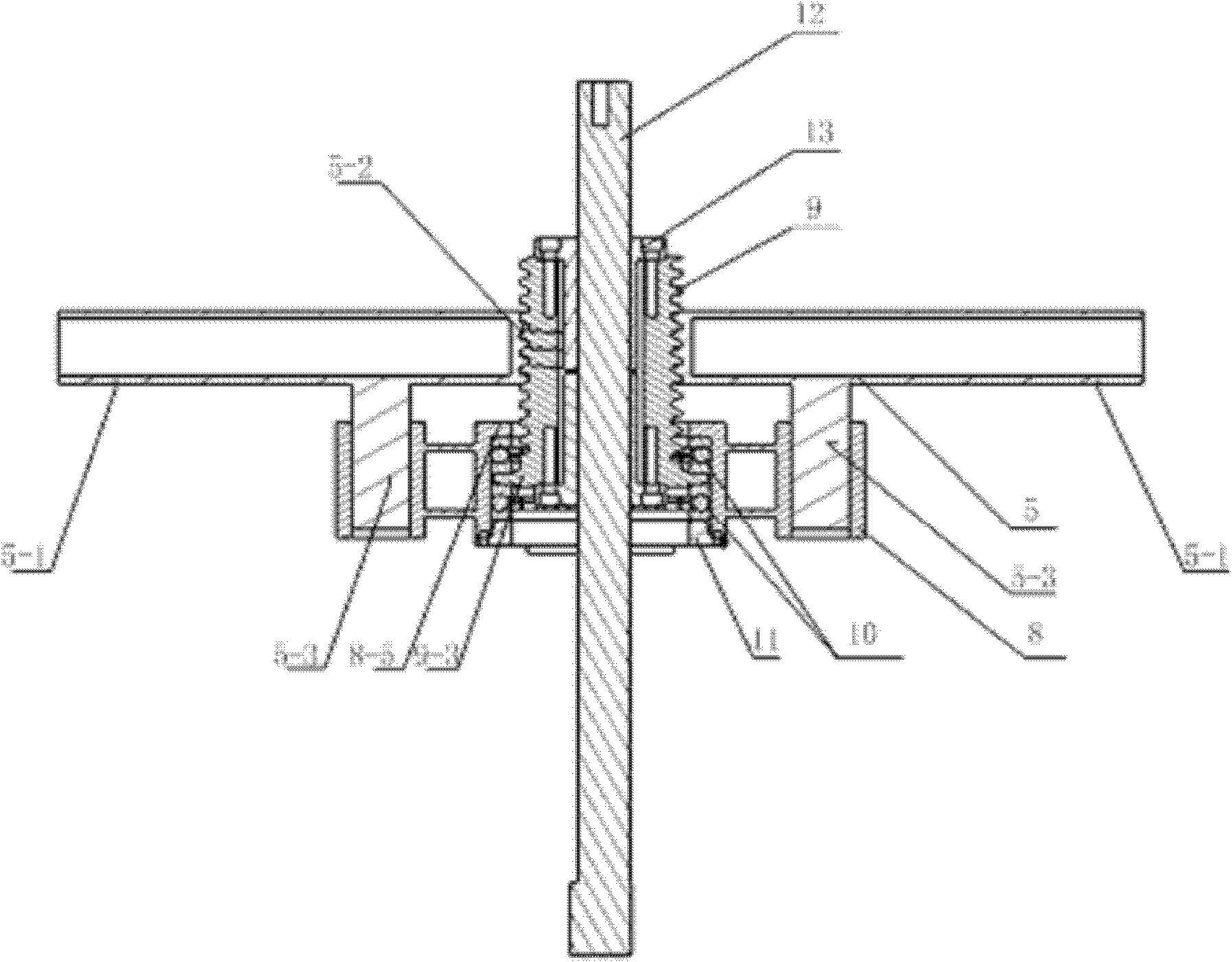
[0026] like figure 1 As shown, the present invention includes a first loading arm 1, two rod end joint bearings 2, two impact loading rods 3, two sets of moving loading cones 4, a second loading arm 5, two bracket arm splints 6, two brackets Arm 7, a mounting bucket 8, a set of threaded sleeves 9, two sets of thrust bearings 10, a cover 11, a spline shaft 12, two flanged splines 13, two pins 14, a joint ball bearing 15 and two support columns 16. The support arm 7 and the support arm splint 6 clamp the support column 16 and connect the support arm 7 and the support arm splint 6 by bolts, and the support arm 7 is connected with the connecting plate 8-4 of the installation bucket 8 with bolts, thus forming the whole The supporting foundation of the structure; such as image 3As shown, two sets of thrust bearings 10 clamp the mounting plate 9-3 of the threaded sleeve 9 and place them on the retaining ring 8-5 of the installation barrel 8, and the cover 11 presses the thrust bea...


PUM


Abstract

The invention relates to an impact loading mechanism comprising two sets of bracket arms, two bracket arm splints, an installation barrel, a seal cover, two sets of thrust force bearings, two sets of movable loading cones, a threaded sleeve, a spline shaft, two flange splines, two loading arms, two rod end joint ball bearings, two support columns, two impact loading rods and a joint ball bearing.The impact loading mechanism can convert the torque of the load input end of the spline shaft into the thrust force of the movable loading cones and apply the thrust force of the movable loading cones to the impact loading rods, and the impact loading mechanism can directly apply the thrust force or pull force of the load input end of the spline shaft to the impact loading rods through the first loading arm. Because mobile blocks on the movable loading cones can be movable or static, the distance between two loading points on a single impact loading rod can change along with time or keep unchanged. Thus, the dynamic synchronous multi-point movement simulation impact loading of the impact loading rods can be realized, and random dynamic or static shearing force and torque can be obtained at the roots of the impact loading rods.

Description

technical field [0001] The invention relates to an impact loading mechanism, which can be used in aviation, aerospace, civil engineering, machinery and other industries, and is suitable for impact loading experiments or product inspections in the range of low and medium frequencies. Background technique [0002] At present, the simulation of impact load is generally fixed-point loading, and mechanical impact is mostly used. Such a loading method is generally difficult to control to obtain the expected design results, and the impact often has a high frequency, which is difficult to produce good effects in some places where low-frequency impact simulation is required. The impact loading mechanism involved in the present invention can be combined with a multi-axis fatigue testing machine to convert the torque output by the fatigue testing machine into a thrust, which can realize synchronous loading of low-frequency multi-point movement of the impact loading rod, and can be used...

Claims


Application Information

Patent Timeline
Patent Type & Authority Applications(China)
IPC IPC(8): G01N3/34
Inventor 石元华程伟刘继奎李晓辉李睿何斌
Owner BEIHANG UNIV
Why Eureka
Try Eureka