System for automatically testing computer mainboard

An automatic test system and computer technology, applied in the detection of faulty computer hardware, etc., can solve the problems of factory operators' management troubles, waste of manpower and material resources in the factory, lack of operating standards, etc., to save manpower configuration and misjudgment, improve Work efficiency and the effect of shortening test time

Inactive Publication Date: 2011-08-17
SUZHOU LONGYU ELECTRONICS EQUIP
View PDF2 Cites 25 Cited by
  • Summary
  • Abstract
  • Description
  • Claims
  • Application Information

AI Technical Summary

Problems solved by technology

The current design is the most direct and intuitive test method, but it has a lot of disadvantages, such as the test takes a lot of time, and the actual insertion will take up a lot of time during the whole test process, and each fixture factory produces There are various test fixture structures, lack of unified standardization, and the operators also lack unified operating standards when they work. Each model must have standard operating instructions and training, which brings great impact to the management of factory operators. Come to trouble, and at the same time, there are certain requirements for the operators
[0003] In addition, it is inevitable that the interface will be damaged during the actual difference of each interface, so that some interfaces become consumables for testing, which will inevitably increase the cost of testing; in addition, there are test operators, and a fixture must be equipped with One operator, this labor-intensive testing method also makes the factory very passive under the current shortage of labor force, which will consume a lot of manpower and material resources of the factory

Method used


Image

  • System for automatically testing computer mainboard
  • System for automatically testing computer mainboard
  • System for automatically testing computer mainboard

Examples


Embodiment

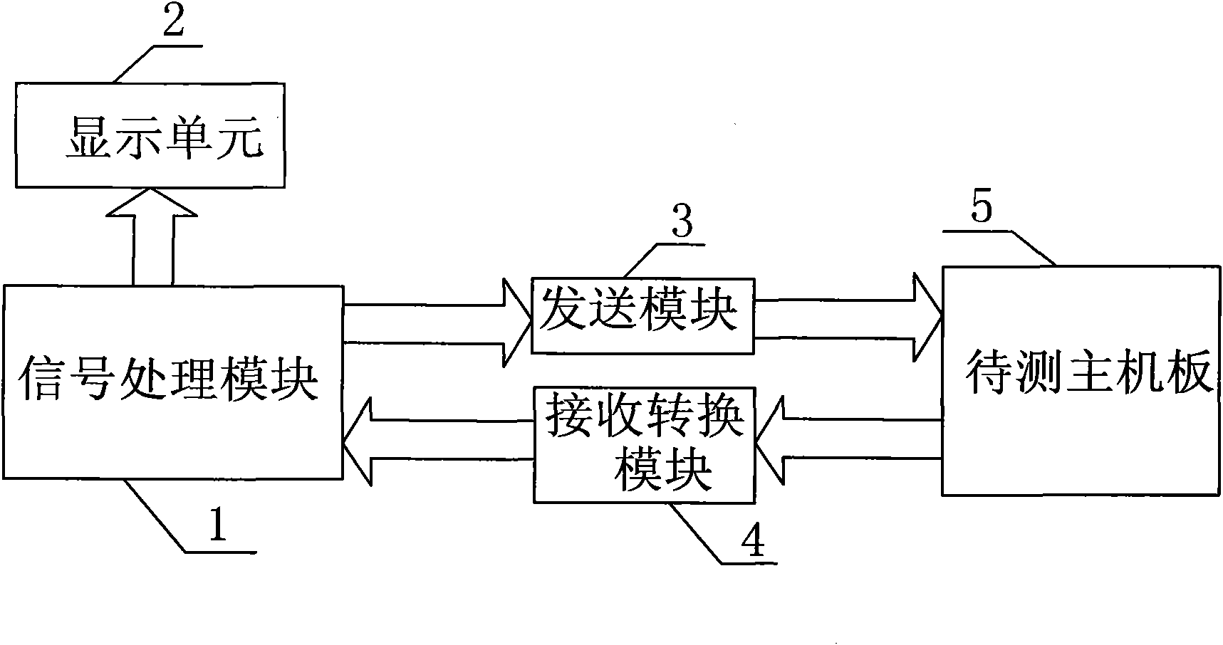
[0035] see figure 1 , computer motherboard automatic test system, including a signal processing module 1, a display unit 2, a sending module 3, a receiving conversion module 4 and a mainboard 5 to be tested.

[0036] The signal processing module 1 is respectively connected with the display unit 2, the sending module 3 and the receiving conversion module 4, wherein the output end of the signal processing module 1 is connected to the display unit 2, and the input end of the sending module 3 is connected to the The output end of the signal processing module 1 is connected to the motherboard 5 to be tested; the input end of the receiving conversion module 4 is connected to the motherboard 5 to be tested, and the output end is connected to the signal processing module 1 .

[0037] The display unit 2 converts various video signals into VGA signals through a video converter, and then detects the quality of the signals through a third-party dedicated video detection device. This metho...


PUM


Abstract

The invention discloses a system for automatically testing a computer mainboard. The system comprises a signal processing module, a display unit, a sending module, a receiving conversion module and a mainboard to be tested; the signal processing module is connected with the display unit, the sending module and the receiving conversion module respectively; the output end of the signal processing module is connected with the display unit; the input end of the sending module is connected with the signal processing module, and the output end of the sending module is connected with the mainboard to be tested; the input end of the receiving conversion module is connected with the mainboard to be tested, and the output end of the receiving conversion module is connected with the signal processing module; the computer mainboard comprises a keyboard part, an audio signal part, a plurality of universal serial bus (USB) interfaces and a video signal part; and a plurality of video signals of the video signal part are uniformly converted into standard video graphics array (VGA) signals for transmission. In the system, the quality of the mainboard to be tested is directly analyzed at a signal end; and the system totally substitutes for manual judgment and test of workers, so the test efficiency is improved greatly, and the accuracy is high.

Description

technical field [0001] The invention relates to the field of computer mainboard function testing, in particular to an automatic testing system for computer mainboard function testing. Background technique [0002] The principle of traditional computer motherboard testing is to use interfaces between modules. For example, after connecting all peripheral circuits such as hard disk, memory, CPU, keyboard, and display to the motherboard, turn on the computer to actually run various test programs, which is equivalent to simulating The actual working conditions of the notebook. The current design is the most direct and intuitive test method, but it has a lot of disadvantages, such as the test takes a lot of time, and the actual insertion will take up a lot of time during the whole test process, and each fixture factory produces There are various test fixture structures, lack of unified standardization, and the operators also lack unified operating standards when they work. Each m...

Claims


Application Information

Patent Timeline
Patent Type & Authority Applications(China)
IPC IPC(8): G06F11/22
Inventor 牛朝军田跃岳佳佳
Owner SUZHOU LONGYU ELECTRONICS EQUIP
Why Eureka
Try Eureka