Electric control radiation directional diagram reconfigurable antenna

A technology of radiating direction and reconstructing antenna, applied in antennas, electrical components and other directions, can solve the problem of narrow application bandwidth of negative refractive index artificial materials, and achieve the effect of low loss, simple antenna structure and high gain

Inactive Publication Date: 2011-08-17
INST OF OPTICS & ELECTRONICS - CHINESE ACAD OF SCI
View PDF3 Cites 21 Cited by
  • Summary
  • Abstract
  • Description
  • Claims
  • Application Information

AI Technical Summary

Problems solved by technology

[0003] The technical problem to be solved by the present invention is: aiming at the problem of narrow application bandwidth of the existing negative refractive index artificial materials, an electronically controlled radiation pattern reconfigurable

Method used


Image

  • Electric control radiation directional diagram reconfigurable antenna
  • Electric control radiation directional diagram reconfigurable antenna
  • Electric control radiation directional diagram reconfigurable antenna

Examples


Embodiment 1

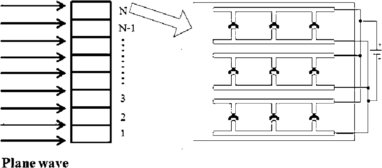
[0032] Such as figure 1 As shown, the implementation process of Embodiment 1 of the present invention is as follows:

[0033] (1) The working frequency is selected as 15GHz, and the corresponding wavelength is 20mm.

[0034] (2) Determine the "I"-shaped artificial structural material unit p x =p y =p z = 2 mm. equal to one-tenth of the wavelength.

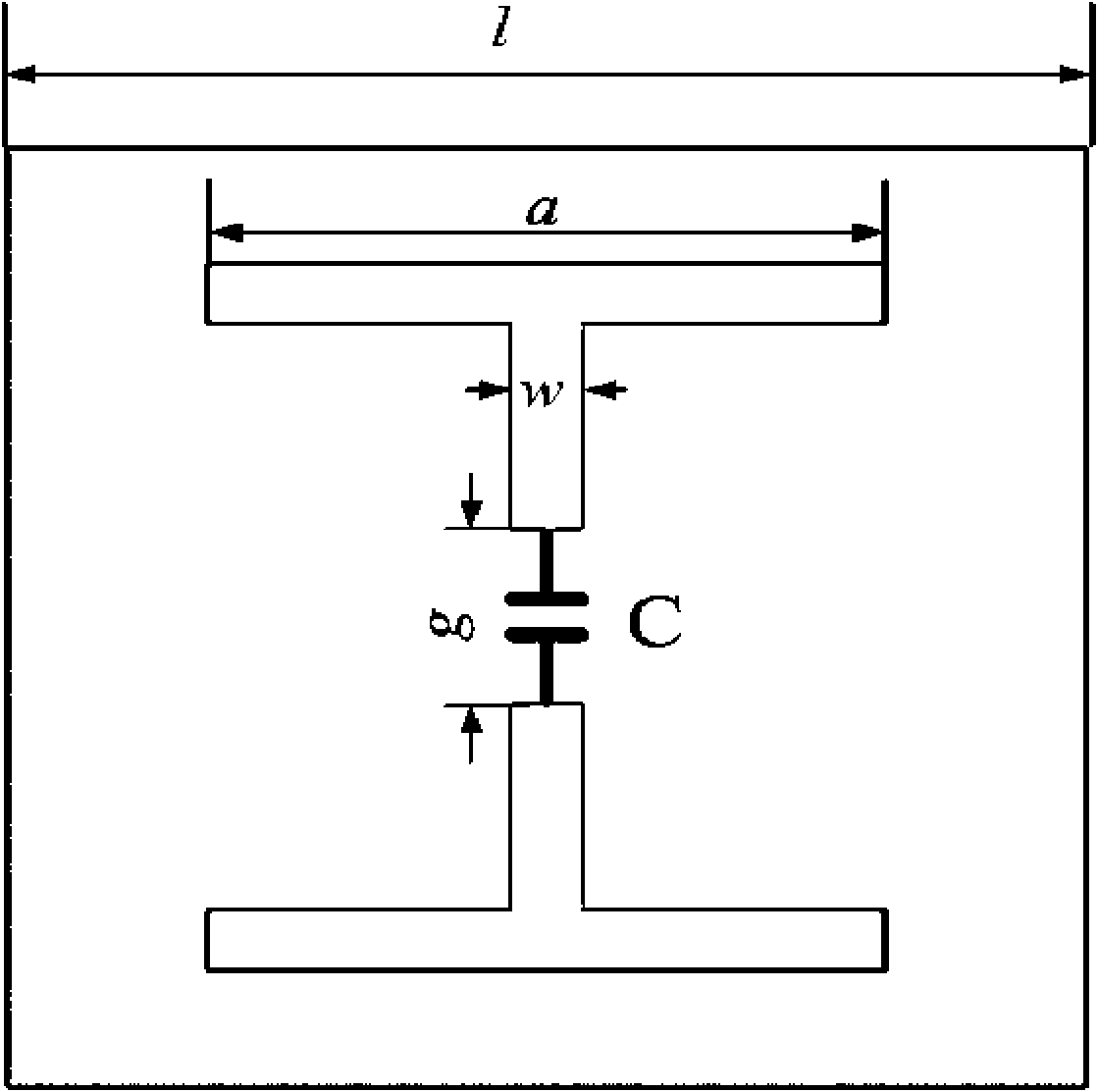
[0035] (3) The selected metal material is copper, and the base material is FR-4.( r =4.9, r =1), metal structure parameters such as figure 2 , Each parameter is l=2mm, w=0.2mm, a=1.8mm, g=0.3mm, FR-4 thickness d=0.25mm, copper thickness t=0.051mm.

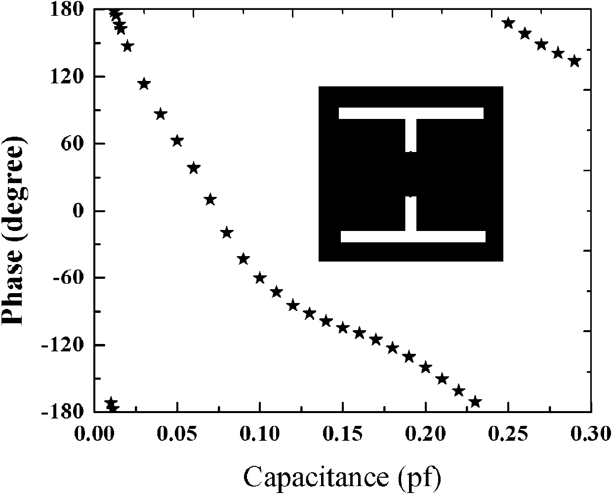
[0036] (4) Since the operating frequency is 15GHz, the type of varactor diode selected here is BB910. When the loading voltage is 0.5V, the capacitance is 38p. When the loading voltage is 8V, the capacitance value is 2.3p. Its capacitance value becomes smaller as the applied voltage becomes larger. (5) Select CST software to simulate and calculate the phase of stacked 10-la...

Embodiment 2

[0041] (1) Select the working frequency as 1.5GHz and the corresponding wavelength as 200mm.

[0042] (2) Determine the "I"-shaped artificial structural material unit p x =p y =p z =20mm, equal to one-tenth of the wavelength.

[0043] (3) The selected metal material is copper, and the base material is Rogers RT / duroid 5880.( r = 2.2, r =1), metal structure parameters such as figure 2 , the parameters are l=20mm, w=0.5mm, a=19mm, g=4mm, the thickness of the base material d=0.5mm, and the copper thickness t=0.051mm.

[0044] (4) The working frequency is 1.5GHz, and the selected variable capacitance diode model is BB134. When the loading voltage is 0.5V, the capacitance is 27.5p. When the loading voltage is 10V, the capacitance value is 1.7p. Its capacitance value becomes smaller as the applied voltage becomes larger.

[0045] (5) Select CST software to simulate and calculate the phase of stacked 10-layer units - Capacitance C curve.

[0046] (6) Similarly, the numbe...


PUM


Abstract

The invention relates to an electric control radiation directional diagram reconfigurable antenna. The reconfiguration of the directional diagram of the antenna is finished by the following steps of: (1) selecting the working frequency f of an antenna; (2) confirming an arrangement cycle of an artificial structure material unit in three directions, an antenna integral structure and a metal structure and the substrate material of a formed unit, wherein the arrangement cycle comprises geometric parameters of the substrate material and the metal structure; (3) adding a variode on an opening of the metal structure; (4) calculating the transmission spectrum S21 phase of the unit by utilizing electromagnetic simulation software, continuously changing a capacitance value of the variode, recording the corresponding phase of a scattering parameter and drawing a phase-capacitance C curve; (5) arranging an artificial material along the horizontal plane cycle, dividing the artificial structure material into N areas with equal distance, and controlling a voltage value loaded on the variode in the unused area, wherein all the areas have equal structural size and contain equal amount of units. The antenna is a controllable antenna of a broadband and can realize positive/negative 40-degree deflection or so of a main lobe of the radiation directional diagram of the antenna.

Description

technical field [0001] The invention relates to a design method for a novel radiation pattern reconfigurable antenna, in particular to a novel antenna for adjusting the antenna radiation pattern by an external voltage. Background technique [0002] In the first decade of this century, artificial artificial structural materials (Metamaterials) attracted more and more attention of scientists for their unique ability to control electromagnetic waves. For example, the negative permittivity and negative magnetic permeability of artificial structure materials make them have very attractive application prospects in negative refractive index lenses, highly directional antennas, superlenses and microwave electromagnetic cloaking. Since the British scientist J.B.Pendry proposed the theoretical prediction that periodic disconnection and periodic arrangement of split rings can realize negative permittivity and negative magnetic permeability in 1996 and 1999 respectively, there has been ...

Claims


Application Information

Patent Timeline
IPC IPC(8): H01Q3/34
Inventor 董小春王义富邓启凌杜春雷
Owner INST OF OPTICS & ELECTRONICS - CHINESE ACAD OF SCI
Why Eureka
Try Eureka