Frame earth stud of solar photovoltaic module capable of eliminating oxide layer

A solar photovoltaic and grounding bolt technology, applied in the direction of screws, nuts, connecting components, etc., can solve the problems of high contact resistance, fire, breakdown of photovoltaic cells, etc., and achieve the effect of low contact resistance, high mechanical strength and simplified operation

Active Publication Date: 2011-08-17
YINGLI ENERGY CHINA
View PDF4 Cites 7 Cited by
  • Summary
  • Abstract
  • Description
  • Claims
  • Application Information

AI Technical Summary

Problems solved by technology

Usually, the connection holes of the ground terminal of the photovoltaic module frame are directly punched or drilled and milled on the aluminum alloy frame profile. When the user installs the ground wire of the photovoltaic module frame, due to the oxide layer or coating on the photovoltaic module frame, As a result, the grounding wire terminal cannot form a good electrical contact with the frame, and the contact resistance is high, so that the grounding wire and the frame cannot form a grounding loop
[0004] According to the requirements of the relevant national electrical grounding resistance standards, the resistance value between the electrical grounding terminal and the earth shall not be greater than 4 ohms to achieve a good grounding effect. If the power supply is incorrectly connected, a good conductive circuit will not be formed between the grounding wire and the aluminum alloy frame, which may cause breakdown or arc flash between the photovoltaic cells, or cause personal electric shock or burn the entire photovoltaic power station. even a fire
[0005] Therefore, before installing the grounding wire to the connecting hole of the grounding terminal, the user needs to remove the oxide layer and coating near the connecting hole of the grounding wire of the frame by mechanical means, and the operation is relatively complicated.

Method used


Image

  • Frame earth stud of solar photovoltaic module capable of eliminating oxide layer
  • Frame earth stud of solar photovoltaic module capable of eliminating oxide layer
  • Frame earth stud of solar photovoltaic module capable of eliminating oxide layer

Examples


Embodiment Construction

[0024] In order to make the above objects, features and advantages of the present invention more comprehensible, the embodiments of the present invention will be further described in detail below in conjunction with the accompanying drawings and specific implementation methods.

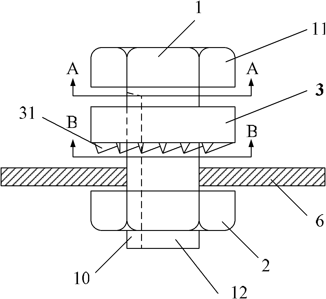
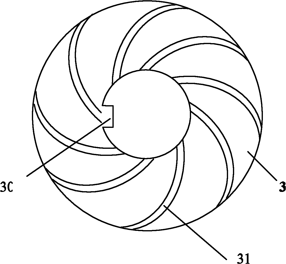
[0025] The invention provides a solar photovoltaic module frame grounding bolt capable of removing the oxide layer, such as figure 1 As shown, the frame ground bolt of the solar photovoltaic module includes a stud 1 , a nut 2 and a scraper 3 .

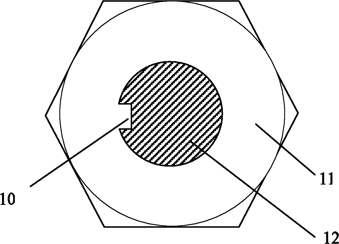
[0026] see figure 2 , The stud 1 includes a stud head 11 and a screw 12, the cylindrical surface of the screw 12 has at least one groove 10 extending along its axial direction. Stud head 11 can be hexagonal stud head, also can be the stud head etc. of circular band slot or Phillips screwdriver groove.

[0027] The nut 2 is screwed on the end of the screw rod 12 away from the stud head 11; when the ground wire is installed, the nut 2 and the stud head 11 are...


PUM


Abstract

The invention discloses a frame earth stud of a solar photovoltaic module capable of eliminating an oxide layer, comprising a stud bolt, a screw nut and a scraping piece, wherein the stud bolt comprises a stud bolt head and a screw; the cylinder of the screw is provided with at least one groove which extends along an axial direction of the screw; the screw nut is in bolted connection with one end, far away from the stud bolt head, of the screw; the scraping piece is sleeved on the screw and arranged between the stud bolt head and the screw nut; a contact surface of the scraping piece and the screw is provided with a lug which is matched with the groove on the stud bolt; and one face facing to the screw nut, of the scraping piece is provided with at least one protruding edge strip. The scraping piece which can realize synchronous rotation with the stud bolt is added at the other side of a frame opposite to the screw nut, so that the oxide layer or a coating is eliminated at a contact position of the frame, thus earth wires electrically contact with a metal frame preferably by the scraping pieces, thereby obtaining lower contact resistance and simplifying operations of installing the earth wires.

Description

technical field [0001] The invention relates to photovoltaic module accessories, in particular to a solar photovoltaic module frame grounding bolt capable of removing an oxide layer. Background technique [0002] The grounding terminal of the traditional aluminum alloy frame solar photovoltaic module is designed on the frame, and the grounding terminal connection hole is processed in advance by the manufacturer of the frame. When the user installs the photovoltaic module, the grounding wire is directly connected to the ground connection hole of the frame, and the ground terminal is connected to the ground through several series and parallel connections between the frame of the photovoltaic module and the connector. [0003] In order to beautify and prevent corrosion of the aluminum alloy frame of the photovoltaic module, anodic oxidation or spraying process is generally used to form a protective layer that is resistant to ultraviolet rays, corrosion and good insulation. Usu...

Claims


Application Information

Patent Timeline
Patent Type & Authority Applications(China)
IPC IPC(8): H01R4/64H01R13/52F16B35/00F16B37/00
Inventor 王士元甄云云陈敬欣
Owner YINGLI ENERGY CHINA
Why Eureka
Try Eureka