Axial flux machine

A technology of axial magnetic flux and machines, applied in the field of generators or motors, new rotor design, can solve the problems of magnetic material deterioration, permanent magnet surface protection damage, complexity, etc., to reduce the risk of surface protection and simplify manufacturing Effect

Inactive Publication Date: 2011-08-17
CUMMINS GENERATOR TECH LTD
View PDF3 Cites 14 Cited by
  • Summary
  • Abstract
  • Description
  • Claims
  • Application Information

AI Technical Summary

Problems solved by technology

However, they are complex and require a clean machining environment and special preparation for the rotor assembly
Furthermore, it has been found tha

Method used


Image

  • Axial flux machine
  • Axial flux machine
  • Axial flux machine

Examples


Embodiment Construction

[0090] Overview:

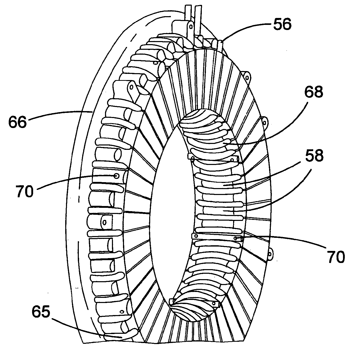
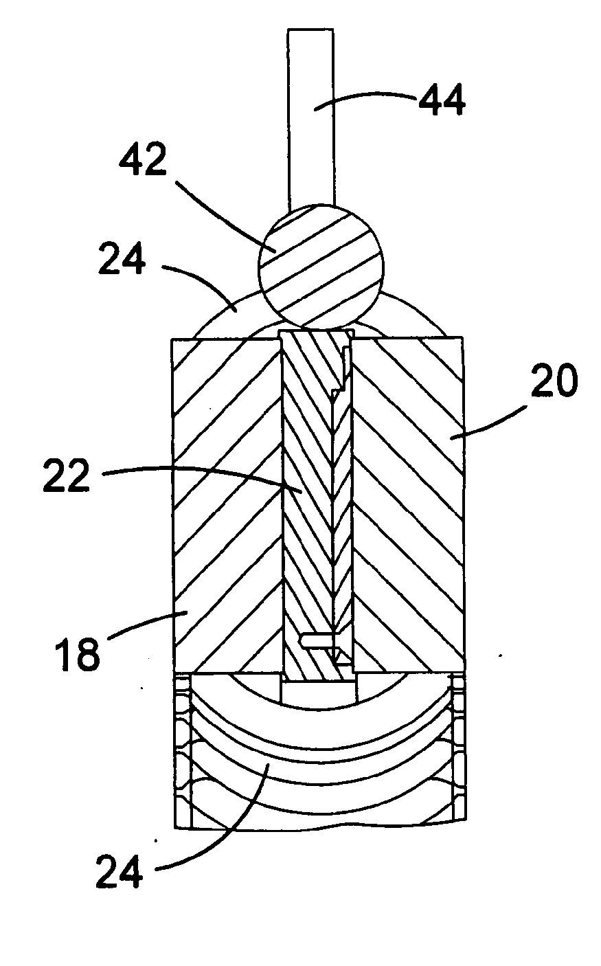
[0091] figure 1 Various components of an axial flux rotating electrical machine are shown. refer to figure 1 , the machine comprises a stator 10 sandwiched between two rotor disks 12 , 14 . The stator 10 includes two slotted laminated toroidal coils 18 , 20 and a cooling jacket 22 sandwiched between the two toroidal coils 18 , 20 . The two stator toroids 18, 20 can be manufactured by rolling a single strip of magnetic steel sheet. The seam 23 is formed on one side by an index punching machine as the rolling process takes place. Stator windings 24 are wound in slots in the finished stator.

[0092] The rotor disks 12, 14 are mounted on a common shaft and may be entirely ferromagnetic. Each disc carries a set of permanent magnets 16 with alternating south and north poles directed axially towards the stator. The rotor carries no alternating magnetic flux, and it can conveniently be constructed of cast iron. Preferably, the permanent magnets 16 are sinte...


PUM


Abstract

An axial flux rotating electrical machine is disclosed, which comprises a stator (10) sandwiched between two rotors (12, 14). The machine comprises retention means (30) for retaining magnets on the rotor, the retention means comprising a back plate (32) with a plurality of protrusions (34) which define a plurality of pockets for accommodating the magnets. The retention means is arranged such that the magnets can be inserted into the pockets and held therein, and the retention means with inserted magnets can be fixed to a rotor so as to retain the magnets axially and tangentially. A cooling jacket (22) for the stator, and techniques for securing the stator to the machine, are also disclosed.

Description

technical field [0001] The present invention relates to an axial flux rotating electrical machine, such as a generator or motor. Aspects of the invention relate to techniques for holding permanent magnets in axial flux machines, techniques for cooling stators in axial flux machines, techniques for holding stators and new rotor design. Background technique [0002] Axial flux rotary electrical machines differ from conventional radial flux machines in that the magnetic flux between the rotor and stator runs parallel to the machine axis. Axial flux machines may have several advantages over radial flux machines, including compact machine construction, high power density, and more robust construction. However, various issues remain to be resolved, including magnetic retention, stator retention and cooling of the machine. [0003] Previous techniques for retaining permanent magnets in axial flux machines include: providing retaining lips on the outer periphery of the rotor disc...

Claims


Application Information

Patent Timeline
IPC IPC(8): H02K1/27H02K21/24H02K9/19
CPCH02K1/12H02K1/20H02K21/24H02K1/2793H02K9/22H02K3/46Y10T29/49012H02K9/227H02K1/2798
Inventor A.梅巴基G.塞尼G.T.蒂亚加拉延M.香内尔A.贝尔R.格雷N.布朗
Owner CUMMINS GENERATOR TECH LTD
Why Eureka
Try Eureka