Injector for injecting high-pressure fuel into the combustion chamber of an internal combustion engine

A technology of injectors and internal combustion engines, applied in fuel injection devices, special fuel injection devices, machines/engines, etc., can solve problems such as injector function failure, erosion, wear, etc.

Active Publication Date: 2011-08-24
ROBERT BOSCH GMBH
View PDF5 Cites 2 Cited by
  • Summary
  • Abstract
  • Description
  • Claims
  • Application Information

AI Technical Summary

Problems solved by technology

When the steam bubble bursts inwards in the region of the control valve, the high local energy density generated here over time leads to erosion on the surface of the wall forming the boundary, thus leading to undesired material erosion and the control valve cause wear on the valve seat
As a result, the surfaces on the valve seat and in the mating area of ​​the valve body are damaged due to cavitation erosion, which can lead to leakage of the control valve, which can lead to functional failure of the injector

Method used


Image

  • Injector for injecting high-pressure fuel into the combustion chamber of an internal combustion engine
  • Injector for injecting high-pressure fuel into the combustion chamber of an internal combustion engine
  • Injector for injecting high-pressure fuel into the combustion chamber of an internal combustion engine

Examples


Embodiment Construction

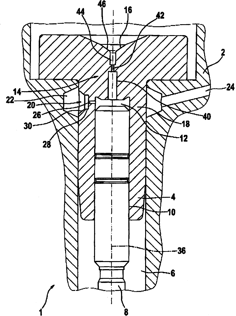
[0025] figure 1 A partial view of an axial section of an injector 1 with a valve section 4 inserted into a housing 2 of the injector 1 is shown. The valve section 4 is arranged here in a multi-staged axial recess 6 of the housing 2 , in which the valve control piston 8 is also received centrally and movable axially and rotationally. exist figure 1 The lower end of the injector housing 2 shown in figure 1 Nozzle body, not shown, in which is arranged a nozzle needle arranged coaxially with respect to the valve control piston 8, which nozzle needle opens the injection nozzles in stages for injecting high-pressure fuel into the internal combustion engine in the combustion chamber.

[0026] An axial bore 10 is provided in the valve section 4 arranged in the injector housing 2 , which extends through the valve section 4 in the axial direction of the valve section and is divided here into zones of different inner diameters. part. In this case, the valve control piston 8 is recei...


PUM


Abstract

The invention relates to an injector for internal combustion engines, comprising a control chamber (12) of a valve control piston (8), said chamber being associated with an inlet bore (20) comprising an inlet throttle (26) for supplying high-pressure fuel and an outlet bore (14) comprising an outlet throttle (42), said outlet bore capable of being closed by a control valve. The high-pressure fuel flowing through the inlet bore (20) is introduced eccentrically into the control chamber (12) and produces within the control chamber (12) a swirling flow, the rotational axis of which extends coaxially to the axis (36) of the outlet bore (14).

Description

Background technique [0001] In injectors known from the field of accumulator injection systems for injecting fuel charged with high pressure into the combustion chamber of an internal combustion engine, the control of the injection process takes place as a function of the position of the control valve assigned to the control chamber of the valve control piston . In this case, the control chamber is fluidically connected via an inlet opening to a high-pressure line via which fuel subjected to high pressure is delivered to the injectors. For pressure relief, the control chamber of the valve control piston is connected to the pressure compensation chamber via an outflow opening, wherein the outflow opening is closed by a pressure-compensating control valve. When the control valve is open, high-pressure fuel flows from the control chamber through the outlet opening into the pressure compensation chamber of the injector, whereby the valve control piston is released. Via the relea...

Claims


Application Information

Patent Timeline
Patent Type & Authority Applications(China)
IPC IPC(8): F02M47/02
CPCF02M2200/28F02M47/02F02M55/008
Inventor M·舍普勒G·魏斯M·普雷斯勒G·塔勒尔M·R·施密德
Owner ROBERT BOSCH GMBH
Why Eureka
Try Eureka