Dynamo electric machine
A technology of rotating electrical machines and torque, applied in synchronous motors with stationary armatures and rotating magnets, electric components, electrical components, etc. question
- Summary
- Abstract
- Description
- Claims
- Application Information
AI Technical Summary
Problems solved by technology
Method used
Image

Examples
no. 1 approach
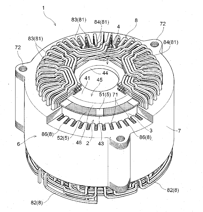
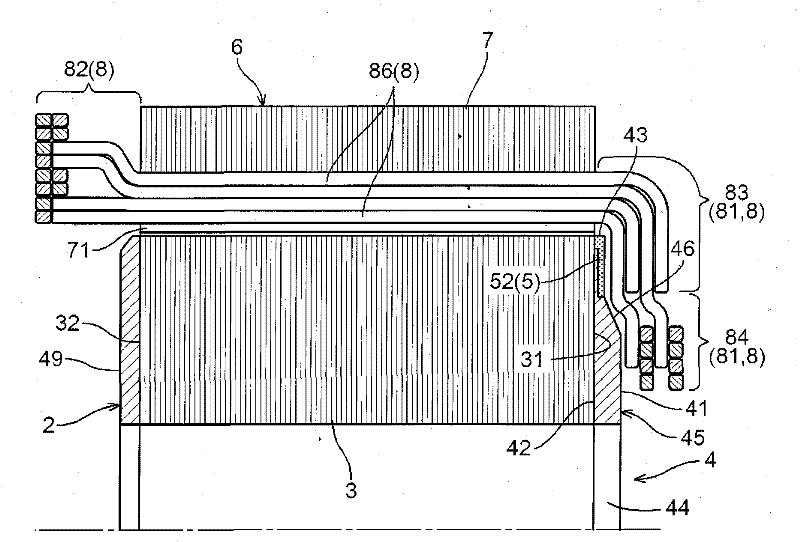
[0042] First, a first embodiment of the present invention will be described based on the drawings. Such as figure 1 and figure 2 As shown, the rotating electric machine 1 of the present embodiment includes a stator 6 in which a coil 8 is wound around a substantially cylindrical stator core 7 , and a rotor 2 rotatably supported radially inward of the stator 6 . In the present embodiment, only one of the two coil end portions 81 , 82 provided on both axially opposite sides of the stator 6 is a bent coil end portion 81 bent radially inward of the stator core 7 . In addition, the rotor 2 includes a substantially cylindrical rotor core 3 and an opposing end plate 4 that faces the bent coil end portion 81 and is attached to the axial end surface 31 of the coil core 3 concentrically with the coil core 3 . . The rotating electrical machine 1 of the present invention is particularly characterized by the configuration of the opposed end plates 4 . Below, refer to Figure 1 ~ Figur...
no. 2 approach
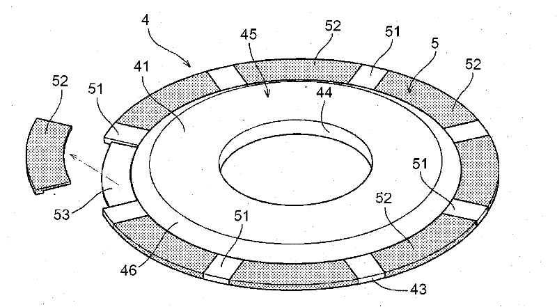
[0064] Below, refer to Figure 4 and Figure 5 A second embodiment of the present invention will be described. The configuration of the opposing end plate 4 of the rotating electrical machine of this embodiment is different from that of the first embodiment described above. That is, the opposing end plate 4 of the present embodiment does not include the permanent magnet 52 , and only includes the salient pole portion 51 as the torque generating portion 5 . That is, this opposing end plate 4 is similar to a member constituted only of the plate main body 45 of the first embodiment described above. In addition, the opposing end plate 4 has a plurality of salient pole portions 51 protruding in a direction approaching the bent coil end portion 81 along the circumferential direction of the opposing end plate 4 .
[0065] The salient pole portion 51 is formed so as to protrude in a direction approaching the bent coil end portion 81 on both the surface 41 and the outer peripheral s...
no. 3 approach
[0068] Below, refer to Figure 6 A third embodiment of the present invention will be described. The structure of the facing end plate 4 of the rotary electric machine 1 of this embodiment differs from that of the said 1st and 2nd embodiment. That is, the opposed end plate 4 of the present embodiment is composed of a powder compact formed by press-molding magnetic powder of a hard magnetic material capable of becoming a permanent magnet. A partially magnetized permanent magnet 52 constitutes the torque generator 5 . Hereinafter, the rotating electrical machine 1 of this embodiment will be mainly described in terms of differences from the first embodiment described above. In addition, in the description of this embodiment, the same configuration as that of the above-mentioned first embodiment will be employed for points that are not particularly mentioned.
[0069]In the present embodiment, the powder compact constituting the opposing end plate 4 is formed by pressure-molding...
PUM
 Abstract
Description
Claims
Application Information
 - R&D
- Intellectual Property
- Life Sciences
- Materials
- Tech Scout
- Unparalleled Data Quality
- Higher Quality Content
- 60% Fewer Hallucinations
Browse by: Latest US Patents, China's latest patents, Technical Efficacy Thesaurus, Application Domain, Technology Topic, Popular Technical Reports.
© 2025 PatSnap. All rights reserved.Legal|Privacy policy|Modern Slavery Act Transparency Statement|Sitemap|About US| Contact US: help@patsnap.com