

Ultrasonic vibration auxiliary grinding method of ultrahard linear microstructural surface
An ultrasonic vibration and microstructure technology, which is applied in the field of ultrasonic vibration-assisted grinding, can solve the problems of destroying the surface accuracy of the microstructure surface, and achieve the effects of reducing the phenomenon of crushing, avoiding interference and high processing efficiency.
- Summary
- Abstract
- Description
- Claims
- Application Information
AI Technical Summary
Problems solved by technology
Method used
Image

Examples
specific Embodiment approach 1
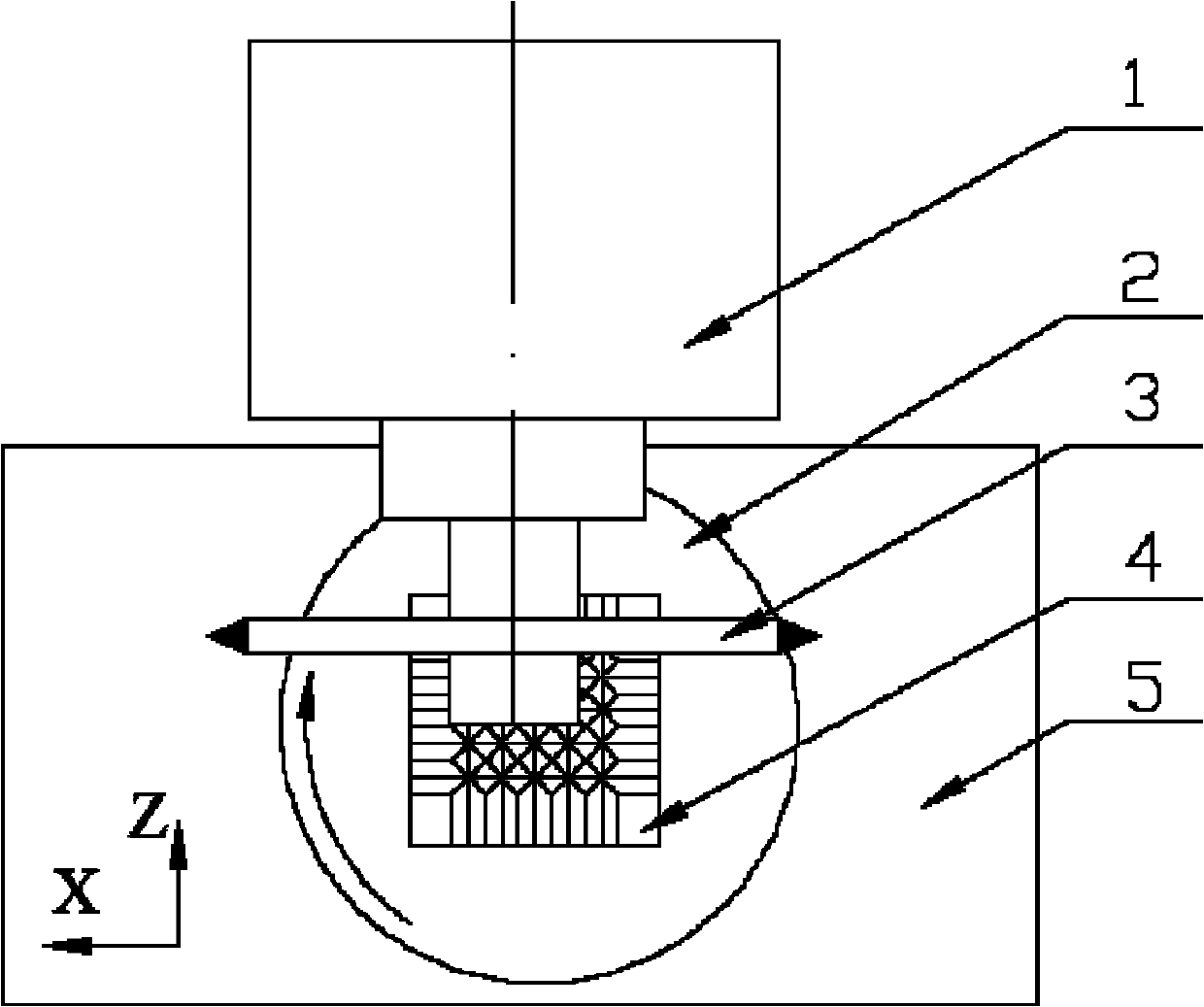
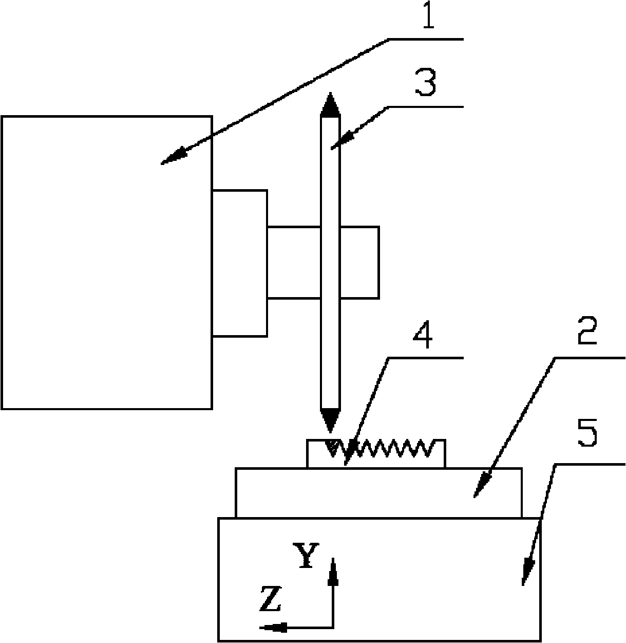
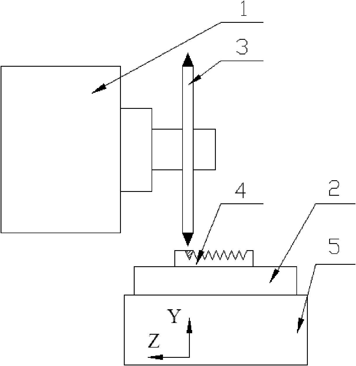
[0014] Specific implementation mode one: combine Figure 1~2 Note that the ultrasonic vibration-assisted grinding method described in this embodiment is implemented according to the following steps:
[0015] Step 1. Install the diamond profiling grinding wheel 3 on the spindle 1 of the plane precision grinding machine tool, install the ultrasonic vibration table 2 on the precision grinding machine table 5, and fix the workpiece 4 to be ground on the upper end surface of the vibration table 2 at the center of
[0016] Step 2. Apply one-dimensional ultrasonic vibration to the vibrating table through the ultrasonic generator, and at the same time drive the workpiece to be ground on the vibrating table to perform one-dimensional ultrasonic vibration. When grinding the parallel linear microstructure surface, that is, the V-shaped groove matrix surface Or the grating microstructure surface, use the rotating table to adjust the vibration direction of the one-dimensional ultrasonic v...
specific Embodiment approach 2
[0018] Specific embodiment two: the rotational speed of the grinding wheel in step two of this embodiment is 3000 rpm. When the grinding wheel speed is 3000rpm, the processing effect is the best, and the surface quality after processing is the highest. Other compositions and connections are the same as those in Embodiment 1.
specific Embodiment approach 3
[0019] Embodiment 3: The ultrasonic vibration amplitude in step 2 of this embodiment is 5 μm. When the amplitude is 5 μm, the vibration effect is the best, and the surface quality after processing is the highest. Other compositions and connections are the same as those in the first or second embodiment.
PUM
 Abstract
Description
Claims
Application Information