Spinning coal mining machine

A technology for a shearer and a fuselage, which is applied in the field of rotary impact shearers, can solve the problems of reduced productivity and block rate, complex and huge structure, large power consumption, etc., and achieves improved work efficiency, good working environment, and power consumption. small effect

Inactive Publication Date: 2011-08-31
刘素华
View PDF6 Cites 8 Cited by
  • Summary
  • Abstract
  • Description
  • Claims
  • Application Information

AI Technical Summary

Problems solved by technology

Its working principle is milling blanking, which determines that the crushing of this mining method is relatively large, especially in the state of compressive stress, which consumes a lot of energy and reduces productivity and block rate
At the same time, the crushing process also produces a large amount of dust, which has caused problems such as bad mining environment and potential safety hazards.
To sum up, the currently commonly used drum shearer mainly has the foll

Method used


Image

  • Spinning coal mining machine
  • Spinning coal mining machine
  • Spinning coal mining machine

Examples


Embodiment 1

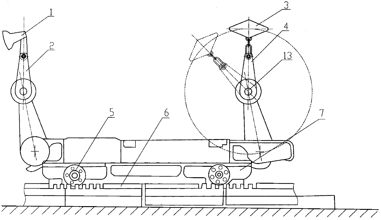
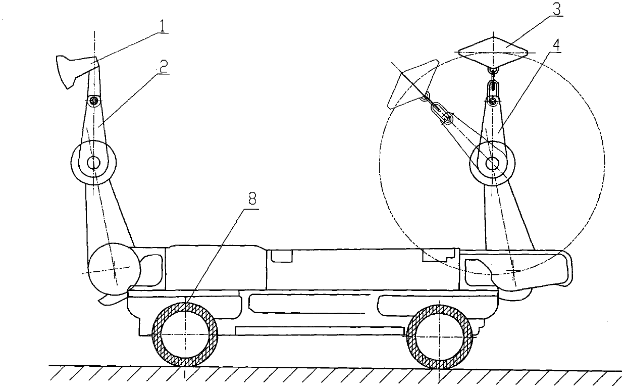
[0031] figure 1 , figure 2 and image 3 It is the rotary percussion shearer described in Embodiment 1. It is composed of a rotary punching mechanism, a driving mechanism and a fuselage. The rotary punching mechanism is installed on the fuselage. The driving mechanism is connected to the rotary punching mechanism. The driving mechanism drives the rotary punching mechanism to rotate. The rotary punching mechanism impacts and cuts the coal seam. device, control device, loading guide device, anti-skid device, dragging cable device, spray device, traction mechanism 7, drive and / or cooling system, etc., traction mechanism 7 pulls the fuselage to walk, and the walking process of the fuselage is related to the rotary punching mechanism The depth of the impacting coal seam is matched and followed up. The body drives the rotary punching mechanism to work and walk. The rotary punching mechanism is installed on the adjustment device. The control device controls the adjustment device to...

Embodiment 2

[0038] like Figure 4 As shown, the punching part of the rotary punching mechanism is the rotary hammer 3, and the hammer heads of the rotary hammer 3 are symmetrically arranged, and the rotary punching mechanism is controlled by the rotation speed and direction control mechanism to control the forward and reverse rotary punching , to achieve forward and reverse coal mining, the control mechanism controls the rotation speed to regulate the depth and volume of coal mining by the rotary punching mechanism.

[0039] Rotary pick hammer 3 is made up of pick hammer head, buffer chain 10, connecting shaft 11, swivel shaft arm 12, swivel shaft 13 and punching hammer buffer device 14, and some auxiliary devices can also be added according to its swivel punching needs. The rotating shaft 13 is connected with the driving mechanism and / or the rotating shaft arm 12 at the same time, and the rotating shaft 13 and the rotating shaft arm 12 rotate simultaneously under the drive of the driving...

Embodiment 3

[0043] like Figure 5Shown is a schematic structural view of the rotary hammer 17, which is connected to the buffer chain 10. The rotary shaft 13 rotates to drive the rotary punching pick 17 for rotary punching coal seam blanking and surface cleaning.

[0044] Others are with embodiment 1 and 2.


PUM


Abstract

The invention relates to mining equipment, particular to a spinning coal mining machine and a method which are used for mining large-sized coal according to the brittle feature of coal by using a spinning mechanism to impact, vibrate and cut coal layers in a rotating way. The spinning coal mining machine comprises a spinning mechanism, a driving mechanism, a machine body and the like, wherein the spinning mechanism is mounted on the machine body; the driving mechanism drives the spinning mechanism to rotate; the spinning mechanism impacts and cuts coal layers; the walking process of the machine body progresses in the match with the depth that the spinning mechanism impacts and cuts the coal layers. If a rotation bush hammer of the spinning mechanism has impact overload during a complete impacting process, by the bending, shifting and the like of a chaining part, a coupling part and an axial buffer part of a rotation arm, the rotation bush hammer can pass smoothly and continuously spins quickly to impact and cut the coal layers to continue coal mining. By the equipment, coal spinning and surface cleaning can be completed synchronously. And the spinning coal mining machine has the advantages of high block material rate, low power consumption, simple structure, stable performance, large mining height range, safety and reliability and the like.

Description

technical field [0001] The invention relates to a mine mining equipment, in particular to a rotary impact shearer. Background technique [0002] The currently widely used mining equipment in mines is the shearer and the plow. Its working principle is milling type blanking, which determines that the crushing of this mining method is relatively large, especially in the state of compressive stress, which consumes a lot of energy and reduces productivity and block rate. At the same time, the crushing process also produces a large amount of dust, causing problems such as poor mining environment and potential safety hazards. To sum up, the currently commonly used drum shearer mainly has the following defects during use: (1) low lump material rate; (2) a lot of dust and harsh working environment; (3) the milling of the cutting part is relatively broken, and the power The consumption is large, there is a large amount of waste of resources, the work efficiency is low, and the cost ...

Claims


Application Information

Patent Timeline
IPC IPC(8): E21C27/12E21C29/22E21C31/02E21C35/00E21C35/24
Inventor 刘素华
Owner 刘素华
Why Eureka
Try Eureka