
Biconical rotary vacuum drying main machine

A vacuum drying and host technology, applied in non-progressive dryers, dryers, drying solid materials, etc., can solve problems affecting product quality and drying efficiency, uneven moisture and fineness of finished products, and unsuitable lithium iron phosphate materials. Drying and other problems, to achieve the effect of convenient replacement, uniform fineness, and improved energy saving

Active Publication Date: 2011-08-31
JIANGSU XIANFENG DRYING ENG
View PDF7 Cites 1 Cited by
  • Summary
  • Abstract
  • Description
  • Claims
  • Application Information

AI Technical Summary

Problems solved by technology

The heat-conducting medium of the above-mentioned double-cone rotary vacuum dryer enters the jacket from one side, and the temperature of the heat-conducting medium drops in the second half, and the jacket becomes "half hot and half cold", resulting in uneven moisture and fineness of the finished product, affecting the quality of the product. Quality and Drying Efficiency
During the drying process of lithium iron phosphate as a battery material, the shape of the material changes greatly from liquid to paste to powder, and the drying of lithium iron phosphate requires controlling the final moisture of the product to be low and the purity high. The above equipment is not suitable. Drying of lithium iron phosphate material

Method used


Image

  • Biconical rotary vacuum drying main machine
  • Biconical rotary vacuum drying main machine
  • Biconical rotary vacuum drying main machine

Examples


Embodiment 1

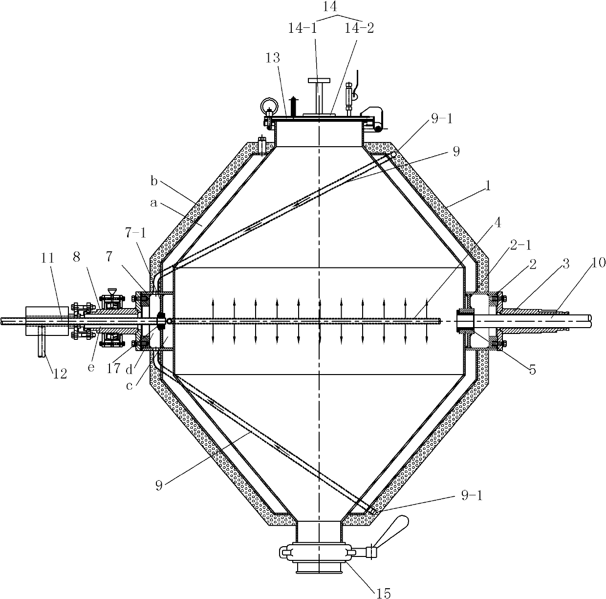
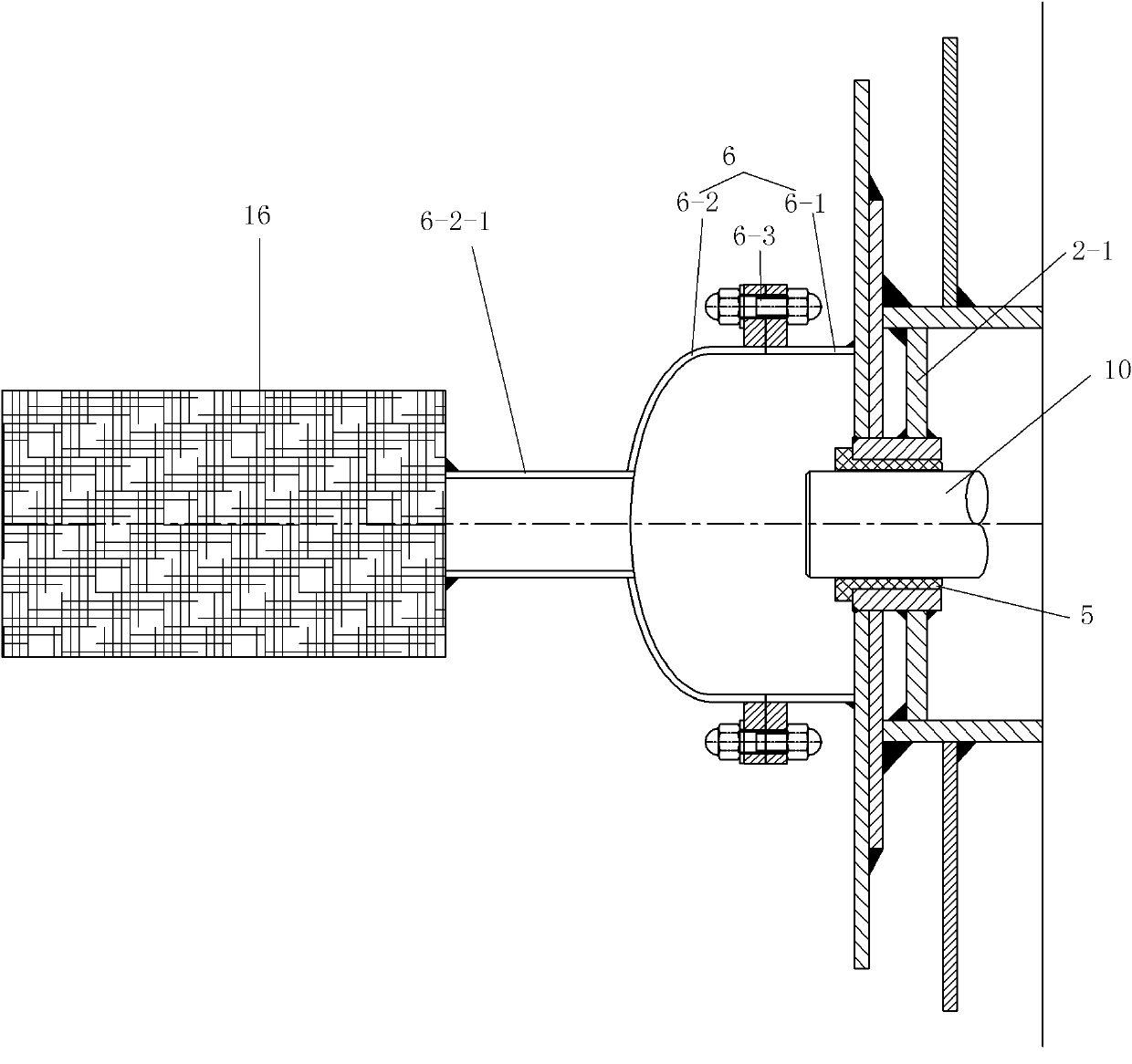
[0016] See Figure 1 to Figure 4 , this embodiment includes a jacketed cylinder body 1, the cylinder body 1 is provided with a feed pipe, a discharge pipe, a driving shaft seat mounting hole and a driven shaft seat mounting hole, and the feed pipe is provided with a feed cover 13, A discharge device 15 is provided on the discharge pipe. The driving shaft seat mounting hole and the driven shaft seat mounting hole are respectively fixed with the driving shaft seat 2 and the driven shaft seat 7 . The main shaft is composed of a hollow driving half shaft 3 and a hollow driven half shaft 8, and the driving half shaft 3 and the driven half shaft 8 are respectively fixed in the driving shaft seat 2 and the driven shaft seat 7. The driving shaft seat 2 is provided with a support plate 2-1, and a tube hole is provided on the support plate 2-1, and the vacuum tube 10 extends into the cylinder body through the inner cavity of the driving half shaft 3 and the tube hole on the support pla...


PUM


Abstract

The invention relates to a biconical rotary vacuum drying main machine, which comprises a cylinder body, wherein two built-in oil supply branch pipes which are arranged horizontally on front and back sides are arranged on the middle part of a clamp sleeve of the cylinder body and are communicated with an oil inlet cavity of a driven shaft base; oil return holes are formed at the positions, which are away from the oil inlet ends of the built-in oil supply branch pipes, at upper and lower ends of the clamp sleeve of the cylinder body; built-in oil return branch pipes which are arranged on upper and lower parts respectively are arranged in an insulating layer of the cylinder body; one end of each of the built-in oil return branch pipes is connected with a corresponding oil return hole on the clamp sleeve, and the other end of each of the built-in oil return branch pipes is inserted into an oil return cavity of the driven shaft base; a gap between an oil supply pipe and the inner wall of a driven half shaft serves as an oil return channel; and one end of the oil return channel is communicated with the driven shaft base, and the other end of the oil return channel is connected with an oil return pipe. By the biconical rotary vacuum drying main machine, heat conducting oil can be distributed to integral clamp sleeve space uniformly to ensure the uniformity of clamp sleeve heating, the problem that biconical rotary vacuum drying is 'semi-hot and semi-cold' for a long term is solved, the quality of products and the work efficiency are improved, and energy is saved.

Description

technical field [0001] The invention relates to a double-cone rotary vacuum drying host. Background technique [0002] Chinese Patent No. 200520073364.9 utility model patent specification discloses a double-cone rotary vacuum dryer, including tank, left arm tube, right arm tube, water inlet pipe, water outlet pipe, vacuum tube, static ring, moving ring, Bearings and sprockets, top springs that can automatically compress the sealing material are provided at the outer ends of the left and right arm barrels, and wear-resistant, sealing Good performance PTFE gasket. The heat-conducting medium of the above-mentioned double-cone rotary vacuum dryer enters the jacket from one side, and the temperature of the heat-conducting medium drops in the second half, and the jacket becomes "half hot and half cold", resulting in uneven moisture and fineness of the finished product, affecting the quality of the product. quality and drying efficiency. During the drying process of lithium iron...

Claims


Application Information

Patent Timeline
Patent Type & Authority Applications(China)
IPC IPC(8): F26B7/00F26B11/04F26B23/00F26B25/08
Inventor 谢洪清查协芳
Owner JIANGSU XIANFENG DRYING ENG
Learn More