
Interleaved power factor corrector with approximate open-loop control

A power factor correction, open-loop control technology, applied in control/regulation systems, output power conversion devices, conversion of DC power input to DC power output, etc. and other problems, to achieve the effect of improving the power level, solving the complex control and low cost

Inactive Publication Date: 2011-08-31
SHANGHAI JIAO TONG UNIV
View PDF5 Cites 19 Cited by
  • Summary
  • Abstract
  • Description
  • Claims
  • Application Information

AI Technical Summary

Problems solved by technology

Although the traditional unit input power factor AC-DC converter has complete functions and high performance, the control is cumbersome, the cost is high, and the ability to withstand voltage and current is limited, so it is not suitable for high-power applications.
[0004] After searching the existing technologies, it was found that "Research and Implementation of High-power Single-phase Digital APFC (Active Power Factor Correction)" (Shanghai Jiaotong University Master's Degree Thesis, January 2009), "New Control Realization of Digital Active PFC with Strategy" (Power Electronics Technology, Issue 2, Volume 44, 2010), Chinese Patent No.: 200410009471.5, Invention Name: Realization of Digital Active PFC with New Control Strategy and Chinese Patent Application No.: 200810146300.5 , Invention name: Air conditioner PFC enabling control method, the PFC circuit described requires a lot of detection, and all need to detect the output voltage, inductor current, etc., especially the detection of the inductor current is cumbersome, and requires input feedforward and output Feedback double closed-loop control, resulting in complex control
In high-power applications, in order to meet higher power level requirements, devices such as power switches with higher withstand voltage and current resistance are required, and the cost is relatively high

Method used


Image

  • Interleaved power factor corrector with approximate open-loop control
  • Interleaved power factor corrector with approximate open-loop control
  • Interleaved power factor corrector with approximate open-loop control

Examples


Embodiment

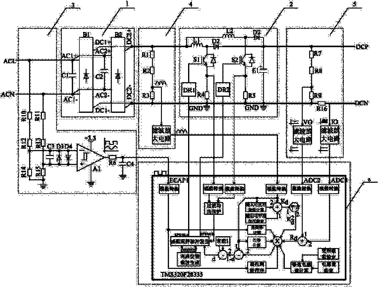
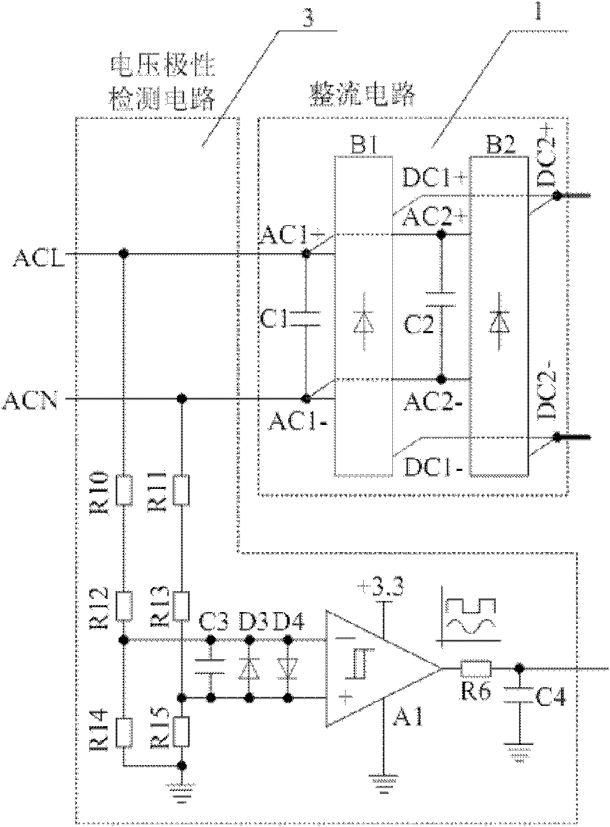
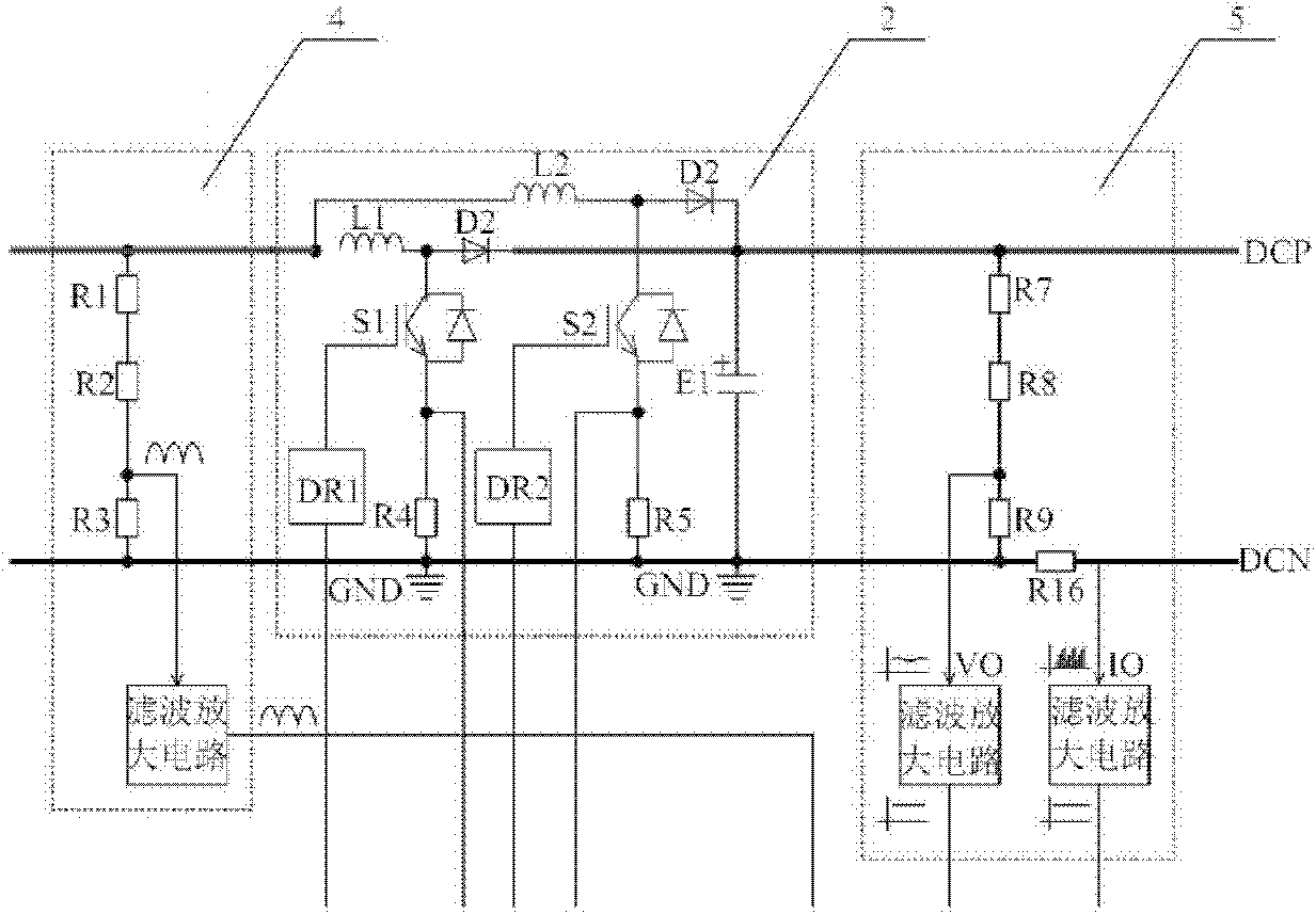
[0024] Such as figure 1 As shown, this embodiment includes: rectification circuit 1, boost circuit 2, voltage polarity detection circuit 3, input voltage detection circuit 4, output detection circuit 5 and control unit 6, wherein: rectification circuit 1 and voltage polarity detection Circuit 3 is connected to the input AC voltage terminal, rectifier circuit 1, input voltage detection circuit 4, boost circuit 2 and output detection circuit 5 are cascaded in sequence, voltage polarity detection circuit 3, input voltage detection circuit 4, boost circuit 2 The sum output detection circuits 5 are connected to the control unit 6, respectively.

[0025] The rectification circuit 1 is composed of a first rectifier bridge B1, a second rectifier bridge B2, a capacitor C1 and a capacitor C2 connected in parallel.

[0026] The input voltage detection circuit 4 includes: a voltage sampling circuit and a filter amplifier circuit composed of a first resistor R1, a second resistor R2 and a...


PUM


Abstract

The invention provides an interleaved power factor corrector with approximate open-loop control in the technical field of power electronics. The interleaved power factor corrector comprises a rectification circuit, an input voltage detecting circuit, a booster circuit, an output detecting circuit, a voltage polarity detecting circuit and a control unit, wherein the rectification circuit, the input voltage detecting circuit, the booster circuit and the output detecting circuit are cascaded with one another in turn; and the voltage polarity detecting circuit, the input voltage detecting circuit, the booster circuit and the output detecting circuit are respectively connected with a control unit. By using the invention, conversion between an alternating current and a direct current is realized; and the interleaved power factor corrector provided by the invention has the advantages of linear input impedance, high power grade, simple structure, easiness in control and low cost.

Description

technical field [0001] The invention relates to a power factor corrector in the technical field of power electronics, in particular to an interleaved power factor corrector with approximate open-loop control. Background technique [0002] The traditional unit input power factor AC-DC converter generally adopts a single-phase PFC (Power Factor Correction, power factor correction) circuit, which needs to detect the input voltage, output voltage and inductor current to form a double closed-loop control of feedforward and feedback. To achieve the requirement of unit input power factor. [0003] With the development of high-power circuits, higher requirements are put forward for the withstand voltage and current resistance of devices. Although the traditional unit input power factor AC-DC converter has complete functions and high performance, the control is cumbersome, the cost is high, and the ability to withstand voltage and current is limited, so it is not suitable for high-p...

Claims


Application Information

Patent Timeline
Patent Type & Authority Applications(China)
IPC IPC(8): H02M1/42H02M3/155
CPCY02B70/126Y02B70/10
Inventor 蒋婷江剑锋曹中圣王虎杨喜军
Owner SHANGHAI JIAO TONG UNIV
Learn More