Light-emitting diode (LED) dynamic scan driving circuit capable of preventing current from overshooting
A light-emitting diode and dynamic scanning technology, which is applied in the direction of electric lamp circuit layout, electric light source, light source, etc., can solve problems such as current overshoot, achieve the effect of improving gray scale, improving display effect, and reducing power consumption
- Summary
- Abstract
- Description
- Claims
- Application Information
AI Technical Summary
Problems solved by technology
Method used
Image
Examples
Embodiment 1
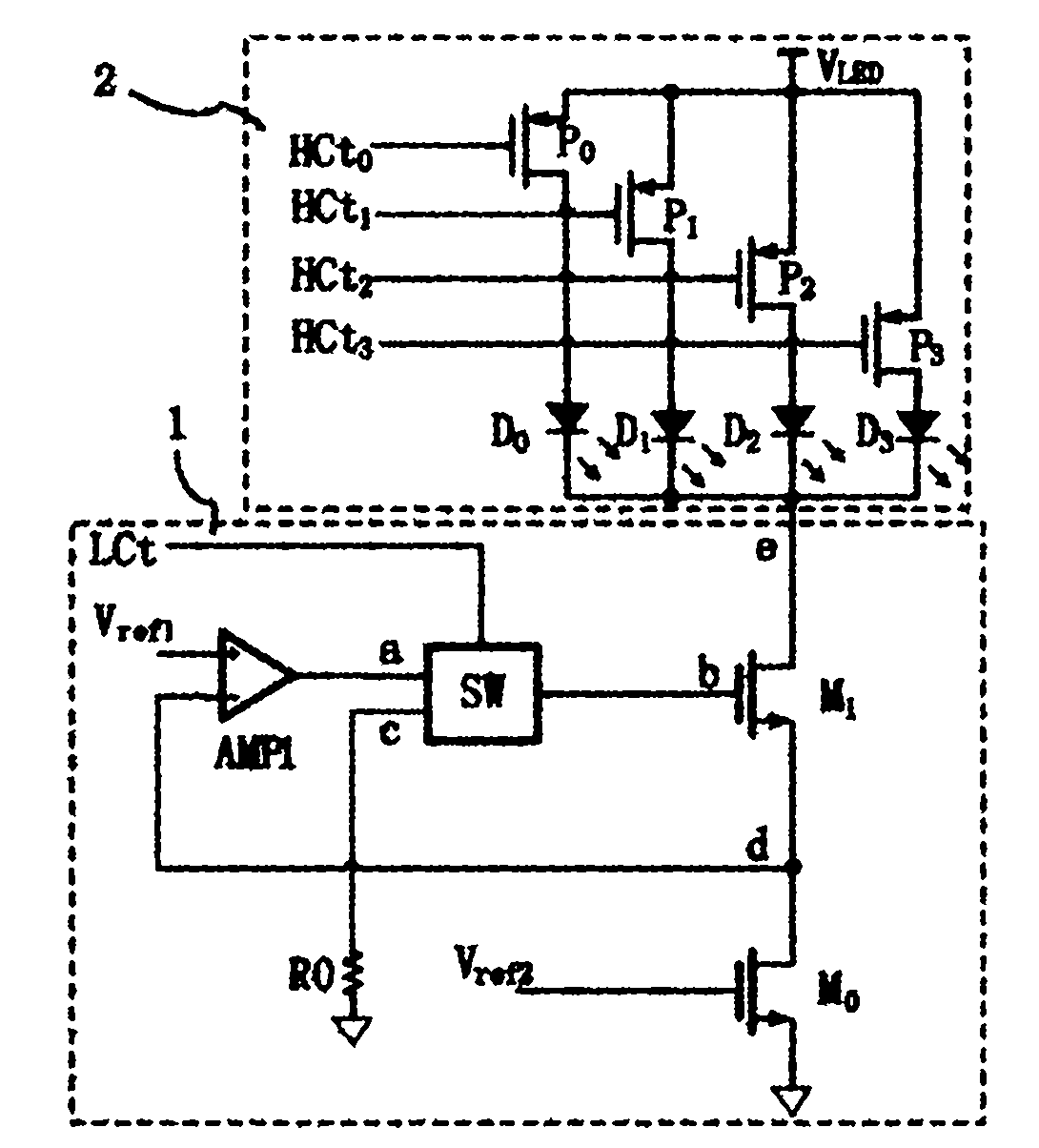
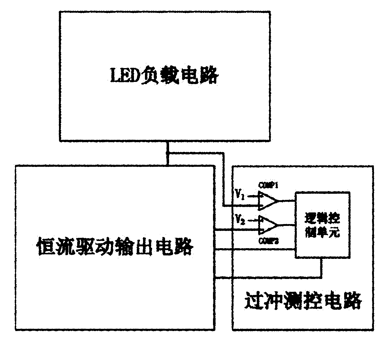
[0038] Such as image 3 with Figure 4 As shown, a light-emitting diode dynamic scanning drive circuit for preventing current overshoot includes an LED load circuit 2, a constant current drive output circuit 1 connected to the LED load circuit 2, and an overshoot measurement and control circuit 3 connected to the constant current drive output circuit 1. .
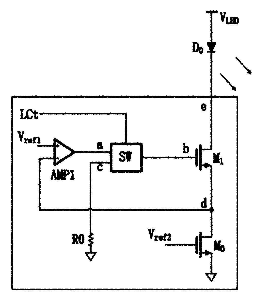
[0039] The constant current drive output circuit 1 consists of an operational amplifier AMP1, a switch unit SW, and a constant current tube M. 0 , Adjustment tube M 1 , Composition of resistance R0.
[0040] The positive input terminal of the operational amplifier AMP1 is connected to the reference voltage V ref1 , The negative input terminal of the operational amplifier AMP1 is connected to the regulator M 1 The source d of the operational amplifier AMP1 is connected to the regulator M through the switch unit SW. 1 The grid b and realize the negative feedback impedance adjustment, forcing the constant current tube M 0 The drain...
Embodiment 2
[0052] Such as Figure 5 As shown, a light-emitting diode dynamic scanning drive circuit for preventing current overshoot includes an LED load circuit 2, a constant current drive output circuit 1 connected to the LED load circuit 2, and an overshoot measurement and control circuit 3 connected to the constant current drive output circuit 1. .
[0053] Constant current drive output circuit 1 is composed of operational amplifier AMP1, switch tube M k , Constant current tube M 0 , Adjustment tube M 1 It is composed of constant current CMOS transmission gate K.
[0054] The positive input terminal of the operational amplifier AMP1 is connected to the reference voltage V ref1 , The negative input terminal of the operational amplifier AMP1 is connected to the constant current tube M 0 The drain of the operational amplifier AMP1 is connected to the regulator M 1 The grid b and realize the negative feedback impedance adjustment, forcing the constant current tube M 0 The drain voltage is equ...
Embodiment 3
[0066] Such as Image 6 As shown, a light-emitting diode dynamic scanning drive circuit for preventing current overshoot includes an LED load circuit 2, a constant current drive output circuit 1 connected to the LED load circuit 2, and an overshoot measurement and control circuit 3 connected to the constant current drive output circuit 1. .
[0067] Constant current drive output circuit 1 is composed of operational amplifier AMP1, switch tube M k , Constant current tube M 0 , Adjustment tube M 1 It is composed of constant current CMOS transmission gate K.
[0068] The positive input terminal of the operational amplifier AMP1 is connected to the reference voltage V ref1 , The negative input terminal of the operational amplifier AMP1 is connected to the constant current tube M 0 The drain of the operational amplifier AMP1 is connected to the regulator M 1 The grid b and realize the negative feedback impedance adjustment, forcing the constant current tube M 0 The drain voltage is equa...
PUM
 Abstract
Description
Claims
Application Information
 - R&D
- Intellectual Property
- Life Sciences
- Materials
- Tech Scout
- Unparalleled Data Quality
- Higher Quality Content
- 60% Fewer Hallucinations
Browse by: Latest US Patents, China's latest patents, Technical Efficacy Thesaurus, Application Domain, Technology Topic, Popular Technical Reports.
© 2025 PatSnap. All rights reserved.Legal|Privacy policy|Modern Slavery Act Transparency Statement|Sitemap|About US| Contact US: help@patsnap.com


