Pressure bonding device and pressure bonding method

A technology of a crimping device and a crimping unit, which is applied to optics, instruments, electrical components, etc., can solve the problems of decreased utilization efficiency, hindered production efficiency, and hindered production efficiency, so as to improve the utilization efficiency and shorten the moving distance. Effect

Active Publication Date: 2011-08-31
PANASONIC CORP
View PDF6 Cites 11 Cited by
  • Summary
  • Abstract
  • Description
  • Claims
  • Application Information

AI Technical Summary

Problems solved by technology

In such a case, the protective sheet cannot be effectively utilized. Especially when dealing with a large-sized panel substrate, the area of ​​the protective sheet that is wound up without being used increases, and the utilization efficiency drops significantly.
If the utilization efficiency of the protective sheet decreases, the frequency of replacement of the supply reel for the protective sheet will increase, and the frequency of stoppage of equipment operations for replacement will also increase, which hinders the improvement of production efficiency.
In addition, in terms of diversification, the frequency of changing the supply reel of the protective sheet may hinder the efficiency of production
In addition, such problems also exist in crimping devices such as ACF bonding devices and parts temporary crimping devices that use protective sheets.

Method used


Image

  • Pressure bonding device and pressure bonding method
  • Pressure bonding device and pressure bonding method
  • Pressure bonding device and pressure bonding method

Examples


no. 1 approach

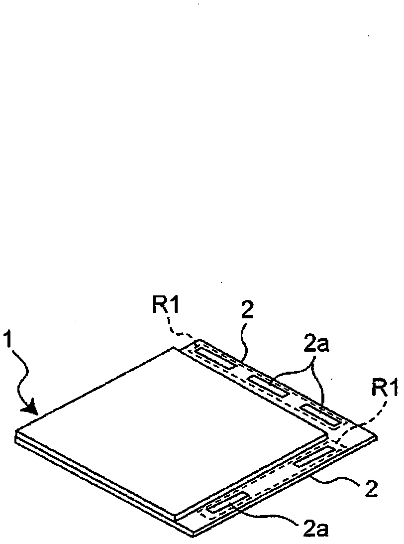
[0086] As an example of the crimping device and method according to the first embodiment of the present invention, a component crimping device and a component crimping method will be described. First, using the figure 1 The form of the panel substrate 1 processed in the above-mentioned component pressure-bonding apparatus and method and the outline of the pressure-bonding process (or mounting process) performed on the panel substrate 1 will be described.

[0087] First, if figure 1 As shown, the substrate to be processed in the first embodiment is a substrate represented by a liquid crystal display (LCD) panel substrate, a plasma display panel (PDP) substrate, etc. (hereinafter referred to as "panel substrate") 1, which Edges of two sides adjacent to each other in the square shape have terminal portions 2 on which component mounting regions R1 for mounting components are disposed. It should be noted that such a panel substrate 1 generally has a rectangular shape, and each te...

no. 2 approach

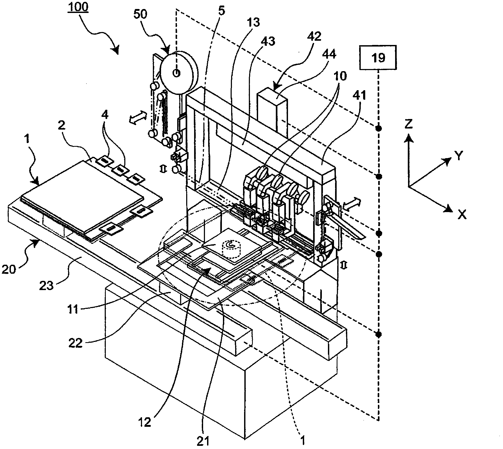
[0147] Next, a crimping method according to a second embodiment of the present invention will be described. The crimping method of the second embodiment is characterized in that the actual crimping device 100 of the above-mentioned first embodiment can selectively respond to the tact of the actual crimping action issued by the operator in terms of control. Prioritize the request or respond to the request from the operator to prioritize the utilization efficiency of the protective sheet. Hereinafter, the crimping method of the second embodiment will be specifically described.

[0148] Here, in order to describe the crimping method of the second embodiment, the moving operation of the protection sheet 5 in the actual crimping device 100 will be summarized. The switching of the contact position of the crimping head 31 relative to the protective sheet 5 by moving the protective sheet 5 in the Y-axis direction, that is, the width direction, by the Y-axis direction sheet moving dev...


PUM


Abstract

A pressure bonding device comprises: pressure bonding units arranged in a row in a first direction and provided with pressing bodies which have pressing surfaces for pressing objects to pressure bonding regions at the edge of a board and also with edge support members for supporting the edge of the board; a protection sheet supply device for supplying a protection sheet in the first direction andspreading the protection sheet along the first direction between the edge support members and the pressing bodies, the protection sheet having a width greater than at least two times the width of thepressing surfaces of the pressing bodies measured in a second direction perpendicular to the first direction, the protection sheet being located between the objects and the pressing surfaces of the pressing bodies to protect the pressing surfaces; and a sheet moving device for the second direction, the sheet moving device being configured to advance and retreat the protection sheet in the second direction, the protection sheet being advanced and retreated within a range not less than the width of the pressing surfaces of the pressing bodies in such a manner the positions of contact of the pressing bodies relative to the protection sheet are switched between each other in the second direction.

Description

technical field [0001] The present invention relates to a pressure-bonding device for pressing an object to be bonded by pressing the pressing body of a pressure-bonding unit against a pressure-bonding region of an edge of a substrate, and in particular to a liquid crystal glass panel substrate, a plasma display panel substrate, and the like. A crimping device and a crimping method for crimping a component or a bonding piece for bonding a component by a crimping region of an edge portion of a substrate. Background technique [0002] Conventionally, components such as electronic components, mechanical components, optical components, flexible printed wiring boards, etc. Substrates such as (FPC substrates) or semiconductor packages such as COG (Chip On Glass), COF (Chip On Film), IC wafers, and TCP (Tape Carrier Package) Components, etc., to manufacture display devices. [0003] A component mounting device (component mounting line) for such a panel substrate (for example, a l...

Claims


Application Information

Patent Timeline
Patent Type & Authority Applications(China)
IPC IPC(8): H01L21/60G02F1/1345H05K13/04
CPCH01L2924/01032H01L21/67092H01L2924/01082H01L24/75H01L24/95H01L2924/0781H01L2924/01004H01L2224/83907H01L2224/838H01L2224/16H01L2924/14H01L24/83H01L2924/01033H01L2224/83192H01L2924/15788Y10T156/1089H01L2924/00
Inventor 森一夫五十岚千寻
Owner PANASONIC CORP
Why Eureka
Try Eureka