Optical signal modulation

A technology of optical signal and optical modulation, applied in the direction of modulation carrier system, optics, nonlinear optics, etc., to achieve the effect of avoiding severe distortion

Active Publication Date: 2011-08-31
TELEFON AB LM ERICSSON (PUBL)
View PDF2 Cites 4 Cited by
  • Summary
  • Abstract
  • Description
  • Claims
  • Application Information

AI Technical Summary

Problems solved by technology

However, it still requires electrical processing of the input bit sequence to apply quadrant differential encoding

Method used


Image

  • Optical signal modulation
  • Optical signal modulation
  • Optical signal modulation

Examples


Embodiment Construction

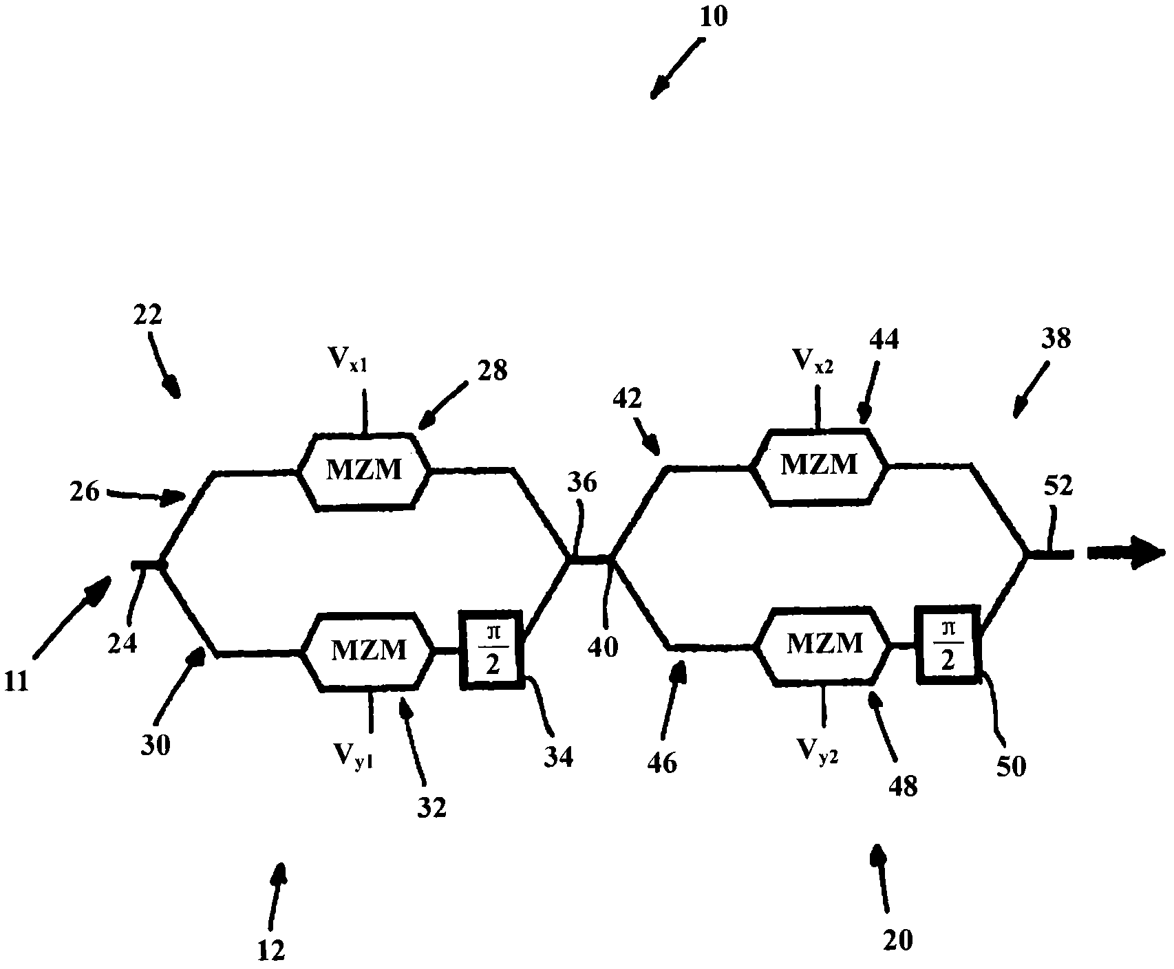
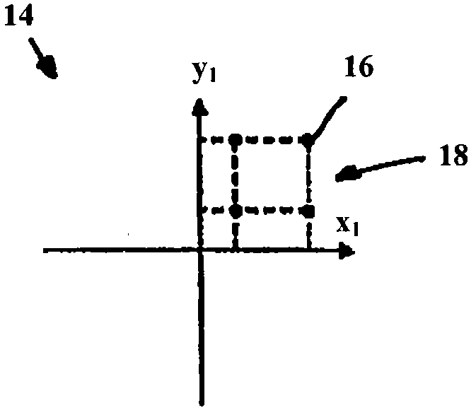
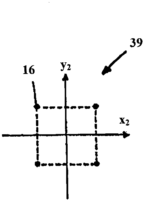
[0074] refer to Figures 1 to 4 , the first embodiment of the present invention provides a 16-QAM optical modulator 10 in the form of 2 n - A quadrature amplitude modulation (QAM) optical modulator comprising an optical input 11 , a first optical modulation device 12 and a second optical modulation device 20 . In this embodiment, an optical signal to be modulated is received by an optical input 11 and coupled to a first optical modulation device 12, which applies a quadrature amplitude modulation scheme to the optical signal, thereby generating an intermediate optical signal. The intermediate optical signal is then fed to a second optical modulation device 20, which is configured to selectively rotate the phase of the intermediate optical signal. The 16-QAM modulated optical signal is thus output from the optical modulator 10, which has such Figure 4 The shown square constellation diagram 19 includes 16 constellation points 16 distributed on 4 quadrants of the constellation...


PUM


Abstract

A 2n-QAM (e.g. 16-QAM) optical modulator 10 comprising cascaded I-Q modulators (22, 38). The first I-Q modulator 22 applies 2n-2 (e.g. 4) QAM to an optical signal, having a constellation diagram with the 2n-2 constellation points located in quadrant I. The second I-Q modulator (38) subsequently applies a quaternary phase-shift keying (QPSK) modulation scheme to the optical signal, thereby rotating the constellation points of the 2n-2-QAM modulation scheme to quadrants II, III and IV, to produce a 2n-QAM modulation constellation diagram. The rotation causes the 2n-QAM modulator to inherently apply four quadrant differential encoding to the optical signal. A method of 2n-QAM optical modulation is also provided and optical signal transmission apparatus comprising the 2n-QAM optical modulator.

Description

technical field [0001] The present invention relates to 2 n Quadrature Amplitude Modulation (QAM) Optical Modulator, 2 n The method of quadrature amplitude modulation and including 2 n - An optical signal transmission device for a QAM optical modulator. Background technique [0002] Quadrature amplitude modulation with 16 levels (16-QAM) is one of the candidate modulation formats for 100 gigabits per second (Gbit / s) transmission into optical fiber. It encodes four bits on a constellation of sixteen points, and transmits the in-phase and quadrature components of the signal with four different amplitude values. When considering the polarization-diverse 16-QAM format for transmission at 100 Gbit / s, the symbol rate required by the transmitter is 12.5 Gbaud. Even at this reduced symbol rate, the generation of multi-level drive signals can be complicated. A further complication arises from the necessity to apply differential digital encoding to the optical signal prior to opt...

Claims


Application Information

Patent Timeline
Patent Type & Authority Applications(China)
IPC IPC(8): H04L27/20H04L27/34H04L27/36H04B10/516H04B10/54H04B10/548
CPCH04B10/541H04B10/548H04L27/36H04B10/5161H04L27/2096H04L27/3488G02F1/225G02F2201/16
Inventor M·塞康迪尼F·卡瓦利耶
Owner TELEFON AB LM ERICSSON (PUBL)
Why Eureka
Try Eureka