Vertical sliding compression mechanism in sliding compression continuous solid-liquid separator

A technology of a solid-liquid separator and a pressurizing mechanism, which is applied in the field of pressurizing mechanisms, can solve problems such as increased production costs, difficulty in pressing, and small footprint, so as to meet the requirements of reducing the site, enhance adaptability, and reduce the footprint Effect

Inactive Publication Date: 2011-09-14
ZHEJIANG HUAZHANG TECH
View PDF9 Cites 2 Cited by
  • Summary
  • Abstract
  • Description
  • Claims
  • Application Information

AI Technical Summary

Problems solved by technology

[0004] 1. Due to the hydraulic reciprocating pressurization, only intermittent operation can be adopted, and the tape running, pressing and unloading must be carried out step by step, so the efficiency is low
In addition, because of the intermittent operation, it is difficult to uniform the cloth, which leads to different pressing effects.
[0005] 2. Since the pressing pressure is completely provided by the hydraulic cylinder, and the stroke of the hydraulic cylinder is limited, the number of filter plates of each equipment is difficult to compare with the traditional box-type filter press. For example, the ordinary plate-type filter press can achieve 100 plates. Above, and the utility model is generally about 10 boards, which is very unfavorable to increase production and reduce equipment cost
[0006] In terms of high dehydration pressure of continuous operation filter press equipment, if the publication date is December 20, 2006, the publication number is CN1879932, and the Chinese patent No. 200610050778.9 discloses "a belt filter press". The filter press uses a steel rope belt to provide high tension to increase the dehydration pressure. The dehydration pressure is as high as 3.0Mpa, which has made substantial progress in increasing the solid content of materials with high friction such as primary sludge filter cake; but , for materials with sticky and slippery properties, such as municipal activated sludge, such a high pressing pressure will inevitably lead to side slipping of materials and difficulty in feeding, making it difficult to implement effective pressing
[0007] In addition, the currently commonly used solid-liquid separator has a large footprint. When the solid-liquid separator is in operation, the required site area is large, especially in the case of wanting to improve work efficiency. More venues, thus greatly increasing the cost of site construction, increasing the work of site maintenance and cleaning
On the other hand, because the currently commonly used solid-liquid separator is easily limited by the size of the site, the adaptability is poor, which brings some inconvenience to the promotion and application of the equipment, especially for some factories with small sites. In order to introduce A set of solid-liquid separator needs to build a special workshop, which not only greatly increases the production cost, but also makes it difficult for the original resources to be rationally utilized, and it is difficult to effectively achieve the requirements of energy saving and emission reduction
[0008] To sum up, there is currently no vertical sliding pressurization mechanism in a sliding pressurization continuous solid-liquid separator that has a small footprint, high production efficiency, can adapt to the dehydration of sticky and slippery materials and operates continuously, so as to provide separation of sticky materials. Slippery materials bring greater inconvenience

Method used


Image

  • Vertical sliding compression mechanism in sliding compression continuous solid-liquid separator
  • Vertical sliding compression mechanism in sliding compression continuous solid-liquid separator
  • Vertical sliding compression mechanism in sliding compression continuous solid-liquid separator

Examples


Embodiment

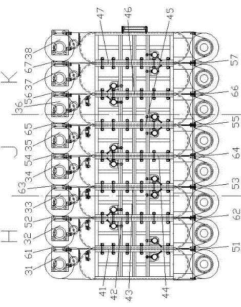
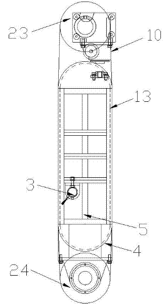
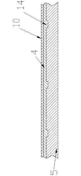
[0045] see Figure 1 to Figure 14 , the vertical sliding pressurization mechanism in the sliding pressurization continuous solid-liquid separator in the present embodiment comprises eight side-by-side pressing units 22, and these eight side-by-side pressing units 22 are No. 1 pressing unit 31 from left to right , No. 2 press unit 32, No. 3 press unit 33, No. 4 press unit 34, No. 5 press unit 35, No. 6 press unit 36, No. 7 press unit 37 and No. 8 press unit 38, and eight press units 22 are Vertical structure, the number of squeezing units 22 in the present invention can be set according to actual needs, as can be determined according to the nature of the material to be squeezed, the desired squeezing effect, etc., the number of squeezing units 22 in the present invention is usually Between 4-20, of course, the number of pressing units 22 is less than four or more than twenty. Since the vertical sliding pressurization mechanism in this embodiment is made up of eight squeeze uni...


PUM


Abstract

The invention relates to a vertical sliding compression mechanism in a sliding compression continuous solid-liquid separator. A vertical sliding compression mechanism with good performance is absent at present. The vertical sliding compression mechanism is characterized by comprising a plurality of parallel squeezing units with vertical structures; each squeezing unit comprises a compression block, an upper compression roller, a lower compression roller, a sliding rubber belt and a transmission belt; the sliding rubber belt coats and winds the compression block; the upper compression roller and the lower compression roller are positioned on the upper side and lower side of the compression block; the transmission belt coats and winds the upper compression roller, the sliding rubber belt and the lower compression roller; a gap is formed between two adjacent squeezing units; and the width of the gap is gradually reduced from a gap inlet to a gap outlet. The vertical sliding compression mechanism is reasonable in structural design, small in occupation area and high in solid-liquid separation efficiency, can be applied to dehydration of an adhesive and slippery material, continuously operates, and can effectively improve the overall performance of the sliding compression continuous solid-liquid separator.

Description

technical field [0001] The invention relates to a pressurization mechanism in a solid-liquid separator, in particular to a vertical sliding pressurization mechanism in a sliding pressurization continuous solid-liquid separator, which belongs to a part of a high-pressure strong solid-liquid separation device. It is mainly suitable for the dehydration of micro-particle liquid materials in sewage treatment plants, paper mills, food processing plants, chemical factories and farms. Background technique [0002] Water treatment plants, paper mills, food processing plants, chemical plants and farms all produce a large amount of materials that need to be dehydrated. These materials are dehydrated, concentrated and then landfilled, which can save a lot of land and reduce sewage infiltration; at the same time, when many organic materials in these materials are concentrated to a certain solid content, they can be directly used for comprehensive utilization, thereby saving drying. Dry ...

Claims


Application Information

Patent Timeline
Patent Type & Authority Applications(China)
IPC IPC(8): B01D25/127
Inventor 唐志超崔健袁帅吴树彬陈伟龙
Owner ZHEJIANG HUAZHANG TECH
Why Eureka
Try Eureka