
Final grinding system of rolling machine in steel slag and mineral slag micropowder production line

A technology of slag micropowder and roller press, which is applied to the final grinding system of roller press of slag micropowder production line and the field of steel slag, can solve the problems of low crushing efficiency, unused, coarse powder particle size, etc., and achieve the effect of protecting the environment

Active Publication Date: 2013-04-10
CHONGQING JINGQING HEAVY MACHINERY
View PDF0 Cites 0 Cited by
  • Summary
  • Abstract
  • Description
  • Claims
  • Application Information

AI Technical Summary

Problems solved by technology

The current grinding process of steel slag and slag grinding production line has two forms: tube mill and vertical mill. The disadvantages of adopting tube mill are: low output and high energy consumption; Pt=1000~1500 KN / ㎡, not only the crushing efficiency is low, the powder particle size is coarse, the specific surface area of ​​the product is low, but also the energy consumption is high and the output is low
The process of using roller press as the main crushing equipment is widely used in cement and other industries, and has the advantage of crushing brittle substances with high hardness and wear resistance, but it has not been used in the final grinding system of roller press in steel slag and slag fine powder production lines

Method used


Image

  • Final grinding system of rolling machine in steel slag and mineral slag micropowder production line

Examples


Embodiment Construction

[0009] Below in conjunction with accompanying drawing and embodiment the present invention will be further described:

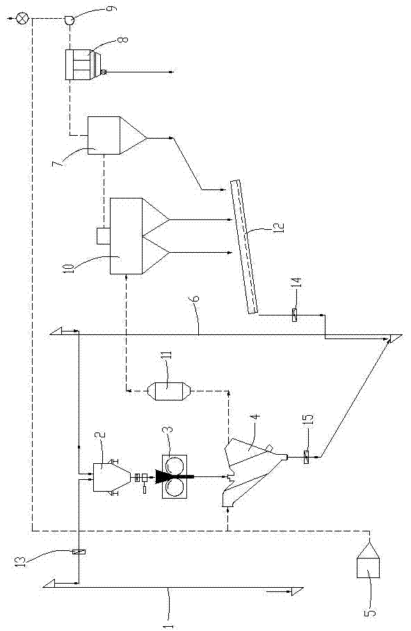
[0010] Such as figure 1 As shown, the present invention consists of a first bucket elevator 1, a steady-flow weighing bin 2, a roller press 3, a V-type powder separator 4, a high-temperature rapid boiling furnace 5, a second bucket elevator 6, and an ultrafine separator 7 , dust collector 8, fan 9, cyclone dust collector 10, drying pipe 11, chute 12, first iron remover 13, second iron remover 14, third iron remover 15 and belt conveyor. A belt conveyor is set between the first bucket elevator 1 and the steady flow weighing bin 2, and the first bucket elevator 1 feeds materials to the steady flow weighing bin 2 through the belt conveyor, and the first bucket elevator 1 and the steady flow weighing bin 2 are fed. A first iron remover 13 is arranged between the steady flow weighing bins 2 . A roller press 3 is arranged below the steady flow weighing bin 2, and...


PUM

PropertyMeasurementUnit
specific surface areaaaaaaaaaaa

Abstract

The invention discloses a final grinding system of a rolling machine in a steel slag and mineral slag micropowder production line. A first hopper type lifting machine feeds materials to a steady-flow weighing bin, and the product of the rolling machine is dispersed and graded in a V-shaped powder concentrator; a high-temperature and high-speed fluidized bed furnace is connected with the air inletof the V-shaped powder concentrator; a drying tube and a rotoclone collector are arranged between the V-shaped powder concentrator and an ultrafine separator; the air outlet of the V-shaped powder concentrator is first connected with the drying tube in series and then connected with the air inlet of the rotoclone collector; the air outlet of the rotoclone collector is connected with the air inletof the ultrafine separator through a pipe; a chute is arranged below the rotoclone collector and the ultrafine separator; and the lowest end of the chute is positioned above the feeding hopper of thesecond hopper type lifting machine. In the invention, through the extruding and crushing of the steel slag and the mineral slag by the rolling machine, and the drying and three-stage powder concentration treatment, steel slag powder and mineral slag powder with a specific surface area of 400 to 550m<2> / kg are provided, the steel slag and mineral slag waste reutilization is realized, and the system has the advantages of changing waste materials into valuable materials, saving energy, reducing emission, protecting environment and the like.

Description

technical field [0001] The invention belongs to the technical field of grinding, and in particular relates to a final grinding system of a roller press in a steel slag and slag fine powder production line. Background technique [0002] Steel slag and slag are important mixed materials for cement production, and steel slag is difficult to break and grind. The current grinding process of steel slag and slag grinding production line has two forms: tube mill and vertical mill. The disadvantages of adopting tube mill are: low output and high energy consumption; Pt=1000~1500 KN / ㎡, not only the crushing efficiency is low, the powder particle size is coarse, the specific surface area of ​​the product is low, but also the energy consumption is high and the output is low. The process of using roller press as the main crushing equipment is widely used in cement and other industries. It has the advantage of crushing high hardness and wear-resistant brittle substances, but it has not be...

Claims


Application Information

Patent Timeline
Patent Type & Authority Patents(China)
IPC IPC(8): B02C4/00B02C23/00B02C23/02B02C23/14
Inventor 张进才胡沿东张珂周俊魏光陆王晓亮李凤昌蒋成福
Owner CHONGQING JINGQING HEAVY MACHINERY
Learn More