
Groove casting technique for large belt pulley

A pulley and casting groove technology, applied in the direction of casting mold, core, casting mold composition, etc., can solve the problems of reduced casting efficiency and machining efficiency, uncontrollable mold matching accuracy, and large machining allowance. Economical, reduce material consumption, improve the effect of bottom shrinkage

Inactive Publication Date: 2011-09-14
天津凯普特动力传输机械有限公司
View PDF6 Cites 13 Cited by
  • Summary
  • Abstract
  • Description
  • Claims
  • Application Information

AI Technical Summary

Problems solved by technology

Due to the thick thermal joints at the junction of the rim and the spokes, defects such as shrinkage and voids are prone to occur at the bottom of the groove after processing, and serious ones will directly cause scrapping
At the same time, due to the large machining allowance due to no casting groove, the material consumption is generally 15-25% higher than that of the casting groove belt pulley, and the large processing volume will also lead to the extension of processing hours.
For this reason, the same industry also adopts the traditional core setting process, that is, 3-8 fan-shaped sand cores (equivalent to Image 6 The middle and middle sand molds are centripetally divided into 3-8 pieces and then matched with molds) to try to cast grooves, but this kind of technology often causes grooves to be dislocated and deformed due to uncontrollable mold matching accuracy, which significantly reduces casting efficiency and machining efficiency , and sand inclusion defects at the core interface will significantly increase tool consumption

Method used


Image

  • Groove casting technique for large belt pulley
  • Groove casting technique for large belt pulley
  • Groove casting technique for large belt pulley

Examples


Embodiment Construction

[0035] In order to further understand the invention content, characteristics and effects of the present invention, the following examples are given, and detailed descriptions are as follows in conjunction with the accompanying drawings:

[0036] 1) Make a model for forming the cavity:

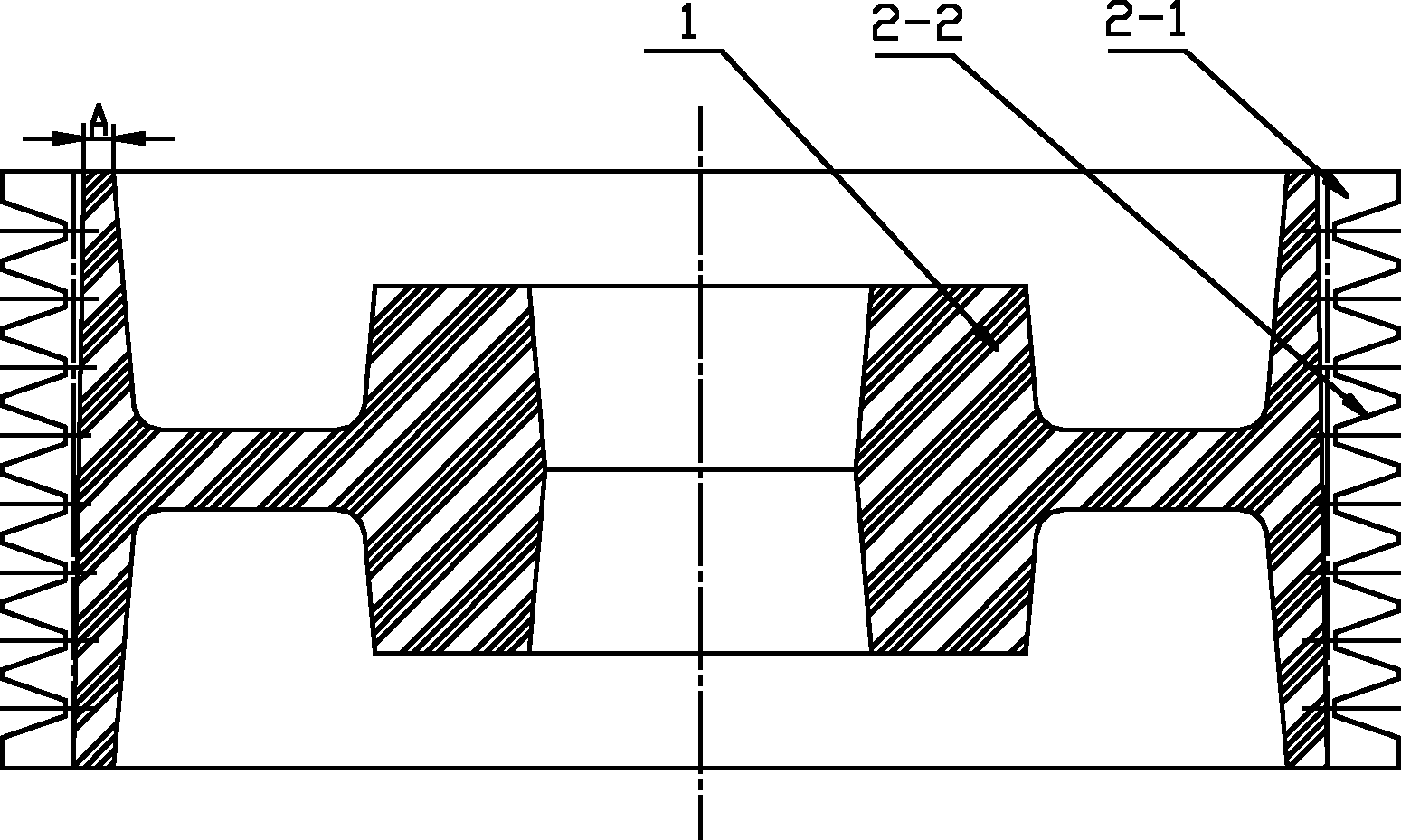
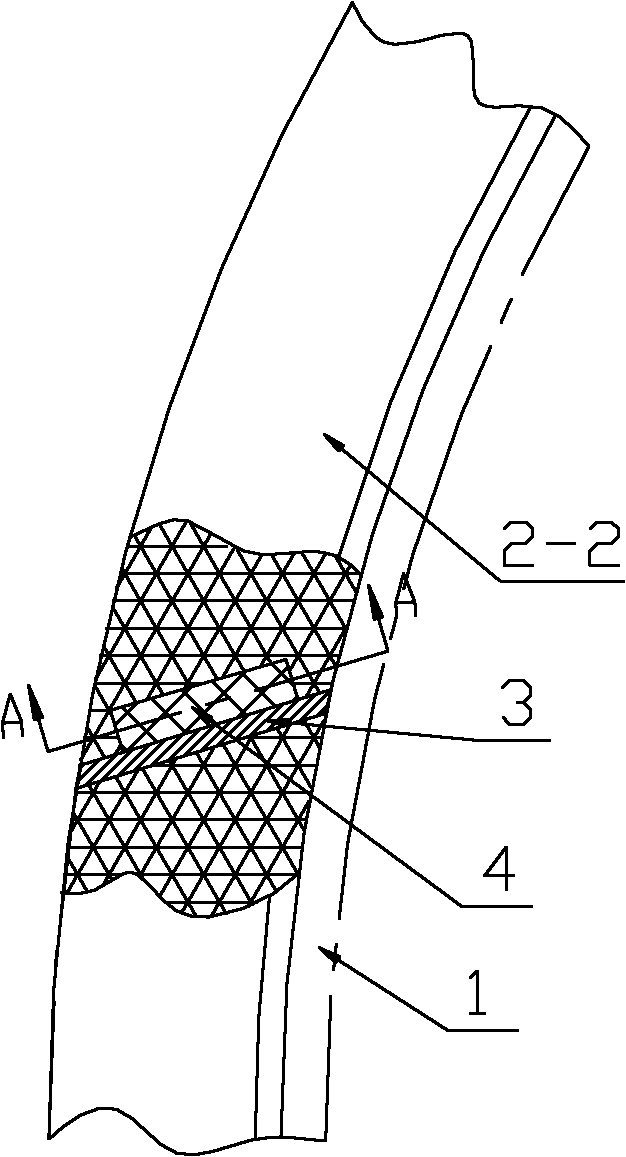
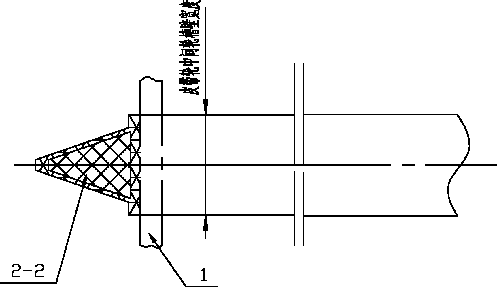
[0037] see Figure 1 to Figure 6 , the model used to form the cavity includes the pulley base model 1 and the number of open annular flexible blocks corresponding to the number of pulley groove walls.

[0038] see figure 1 , the pulley base model 1 is a cast nylon model adapted to the shape of the pulley; the outer surface of the pulley base model 1 is provided with a draft slope of 15' to save the gap between the pulley base model 1 and the open annular flexible block The sliding surface between them is convenient for the ejection operation of the molding process. It should be noted that the draft angle of the outer surface of the pulley base model 1 is 15', which is schematic and not rest...


PUM


Abstract

The invention discloses a groove casting technique for a large belt pulley, comprising the following steps of: firstly, manufacturing a model for forming a cavity, which comprises a belt pulley matrix model and opened annular flexible movable blocks in which the number is corresponding to that of the groove walls of the belt pulley; secondly, forming a middle sand mould, wherein a belt pulley groove-casting combined model formed by the belt pulley matrix model and the opened annular flexible movable blocks is arranged inside the middle sand mould; thirdly, forming an upper sand mould; fourthly, turning over a box; fifthly, forming a lower sand mould; and sixthly, forming a belt pulley groove-casting cavity. Based on self-hardening sand technique, an inner locating three-box shape is adopted, the opened annular flexible movable blocks form groove profiles, and the thickness of the thermal center of the rim part of the belt pulley can be effectively decreased by relying on the combined mould technique located for belt pulley matrix mould so that the groove-bottom shrinkage porosity and shrinkage cavity tendency are obviously improved; and simultaneously, 15-25% of material consumption is reduced, the machining cost is obviously reduced, and the technique has high production efficiency. The groove casting technique is suitable for being used for the casting of a large belt pulley groove with a diameter of larger than 400 mm.

Description

technical field [0001] The invention relates to a casting method of a self-setting grinding wheel groove, in particular to a large-scale pulley groove casting process. Background technique [0002] Furan resin self-setting sand casting large pulleys generally adopt the non-cast groove type. Due to the thick heat joint at the junction of the rim and the spokes, defects such as shrinkage and voids are prone to appear at the bottom of the groove after processing, and serious ones will directly cause scrapping. At the same time, due to the large machining allowance due to no casting groove, the material consumption is generally 15-25% higher than that of the casting groove pulley, and the large processing volume will also lead to the extension of processing hours. For this reason, the same industry also adopts the traditional core setting process, that is, 3-8 fan-shaped sand cores (equivalent to Figure 6 The middle and middle sand molds are centripetally divided into 3-8 piec...

Claims


Application Information

Patent Timeline
IPC IPC(8): B22C9/22B22C9/28
Inventor 董贵军潘秀峰桂阳
Owner 天津凯普特动力传输机械有限公司
Learn More