Dynamic sail wind energy machine and rotation and revolution control method thereof

A wind turbine and power technology, which is applied in the control of wind turbines, engines, and wind energy generation, etc., can solve problems such as the bottleneck of wind energy and electric energy conversion efficiency, the resistance of wind blades working against the wind, affecting the utilization rate of wind energy, etc., and achieve strong field survivability. , Improve the utilization rate of the whole machine, the effect is unique

Inactive Publication Date: 2011-09-14
吴兆 +1
View PDF9 Cites 9 Cited by
  • Summary
  • Abstract
  • Description
  • Claims
  • Application Information

AI Technical Summary

Problems solved by technology

[0006] 2. The safety is limited, the material technical requirements are high, and the price is expensive
However, since the rotation and revolution of the blades of the above-mentioned wind energy machine are driven by a specific transmission mechanism, and the rotation speed ratio of the rotation axis of the blades to the rotation axis around the revolution axis is 1:2, in the entire revolution period, only when the blades reach The highest operating efficiency can be obtained only when the downwind point and the upwind point are reached, and when the blades are in other upwind positions on the upwind side, the wind blades will still generate a lot of resistance when doing work against the wind, and at the same time, when the blades are in other positions on the downwind side , which is far from the operating efficiency that can be achieved at the downwind point, forming a slowly increasing and attenuating work state, which affects its wind energy utilization rate
Due to the above-mentioned wind energy machine adopting the specific transmission structure for the transmission control of the rotation and revolution of the wind blades, the conversion efficiency of wind energy and electric energy has reached a bottleneck state and cannot be improved.

Method used


Image

  • Dynamic sail wind energy machine and rotation and revolution control method thereof
  • Dynamic sail wind energy machine and rotation and revolution control method thereof
  • Dynamic sail wind energy machine and rotation and revolution control method thereof

Examples


Embodiment Construction

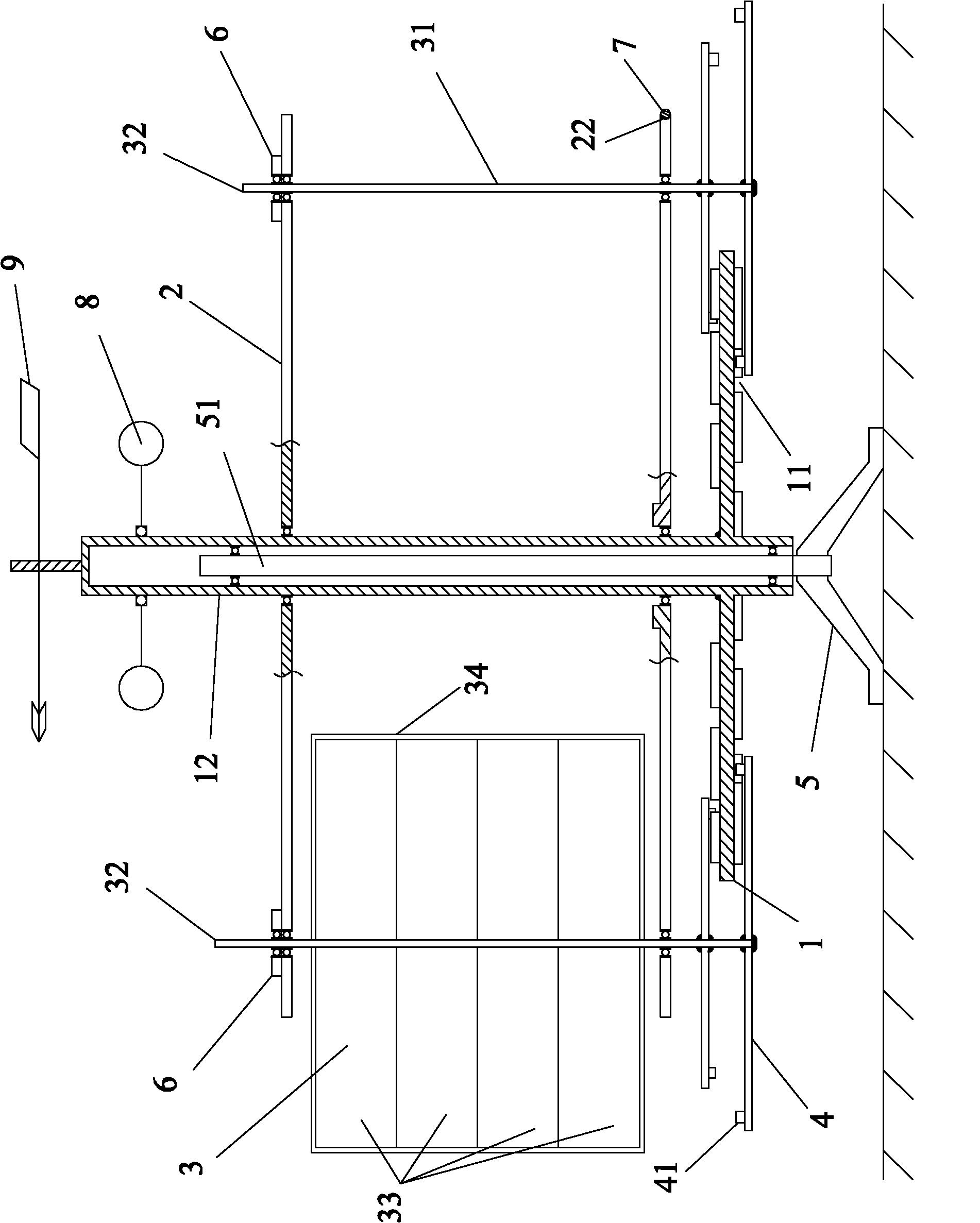
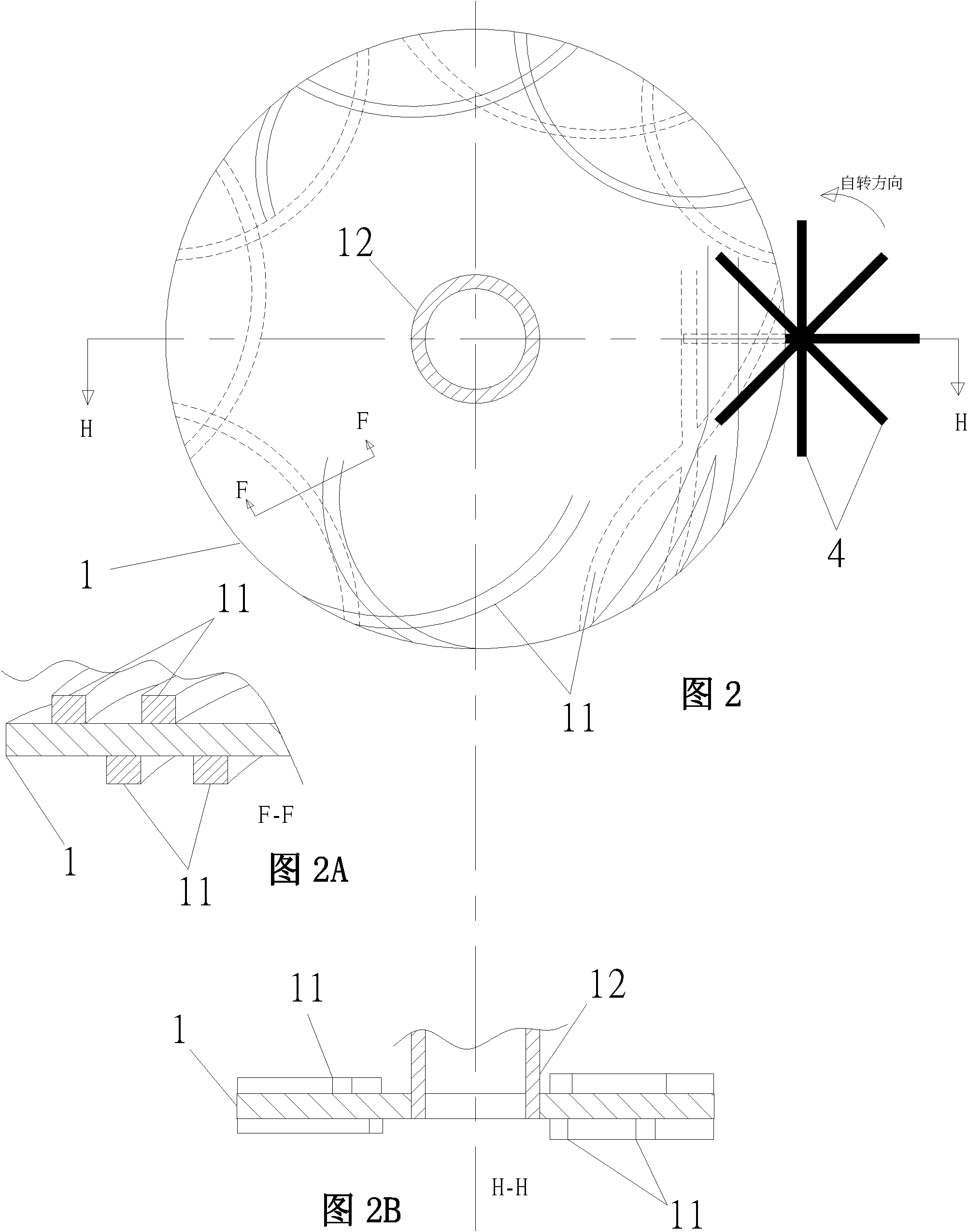
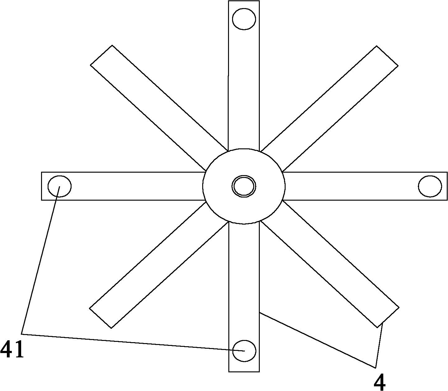
[0045] A power sail wind energy machine of the present invention includes a main shaft, a guide plate, a rotating bracket and a sail assembly, the rotating bracket can revolve around the main shaft, and the sail assembly can rotate on the rotating bracket; and the rotation and The direction of revolution is opposite; wherein, the guide track provided on the guide plate is arranged in cooperation with the sail assembly, and controls the rotation of the sail assembly on a preset track, and the rotation is a non-uniform rotation; in the sail assembly In one revolution period, according to the different included angles between the sail and the wind direction of the sail assembly, there is a tailwind maximum resistance state area corresponding to a first revolution angle (revolution angle A), and in the tailwind maximum resistance state area, the Said sail is perpendicular to the wind direction.

[0046] The present invention also proposes a control method for the rotation and revo...


PUM


Abstract

The invention discloses a dynamic sail wind energy machine which comprises a main shaft, a bootable disk, a rotating bracket and sail components, wherein the rotating bracket can revolve around the main shaft, the sail components can rotate on the rotating bracket, and the rotation direction is opposite to the revolution direction; a guiding track arranged on the bootable disk is matched with thesail components and controls the sail components to rotate on the preset track, and the rotation is non-uniform rotation; within a period of revolution of the sail components, according to the different included angles formed by the sail of the sail components and the wind direction, a downwind maximum resistant state region which corresponds to the first revolution angle is formed, the sail and the wind direction can be vertically orthogonal within the downwind maximum resistant state region. According to the invention, the working efficiency of the sail can be effectively improved.

Description

technical field [0001] The invention relates to a wind energy machine, in particular to a power sail wind energy machine which can effectively improve the working efficiency of the sail. Background technique [0002] At present, wind turbines are mainly horizontal-axis propeller-type lift wind energy machines. Although the technology of this type of wind turbine is very mature, it has its inherent limitations: [0003] 1. Low efficiency. [0004] (1) The sail is based on the working principle of lift. Although the linear speed is high during work, the wind pressure difference between the windward side and the leeward side of the blade is not large, so it is difficult to fully utilize the wind energy. [0005] (2) The working area of ​​the blade only accounts for less than 10% of the "sweeping area", and only the middle and root are working parts in the whole blade, and the wind energy consumption tends to develop towards the blade end. [0006] 2. The safety is limited, th...

Claims


Application Information

Patent Timeline
Patent Type & Authority Applications(China)
IPC IPC(8): F03D3/02F03D11/04F03D3/06F03D7/06
CPCY02E10/728Y02E10/74Y02E10/72
Inventor 吴方
Owner 吴兆
Why Eureka
Try Eureka