
Microstructural stereoscopic anaglyph image-text platemaking method and device

A technology of three-dimensional relief and microstructure, which is applied in the direction of photolithography exposure device, microlithography exposure equipment, etc., to achieve the effect of beautiful packaging and advanced anti-counterfeiting function

Active Publication Date: 2011-09-14
中丰田光电科技(珠海)有限公司
View PDF6 Cites 11 Cited by
  • Summary
  • Abstract
  • Description
  • Claims
  • Application Information

AI Technical Summary

Problems solved by technology

[0003] Aiming at the deficiencies of the above existing three-dimensional graphic printing technology, the present invention provides a brand-new high-energy beam plate-making method, which can produce a microstructure pattern plate with a three-dimensional relief effect that can be seen with the naked eye under ordinary light, so as to solve the existing problems. In technology, the depth and angle control of optical interference patterns and the design of microstructure patterns are two major technical problems in the production of three-dimensional microstructure plates

Method used

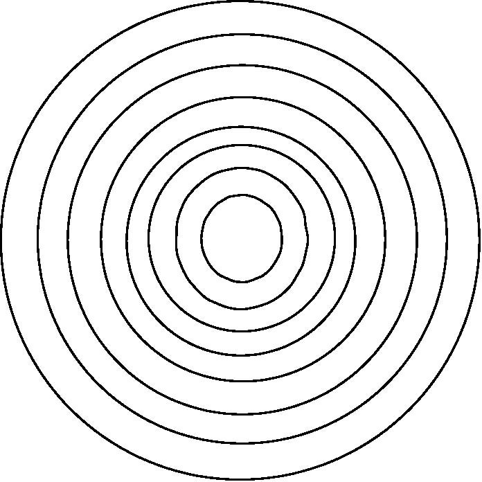
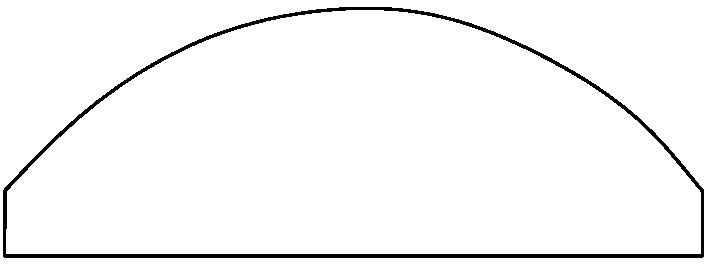

Image

  • Microstructural stereoscopic anaglyph image-text platemaking method and device
  • Microstructural stereoscopic anaglyph image-text platemaking method and device
  • Microstructural stereoscopic anaglyph image-text platemaking method and device

Examples


Embodiment Construction

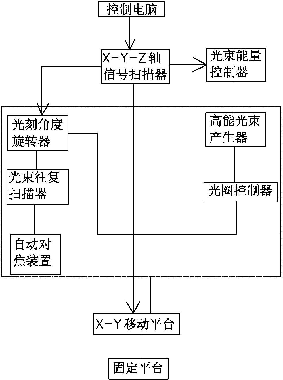
[0020] Such as figure 1 As shown, the microstructure three-dimensional relief graphic plate-making device of this embodiment includes a control computer, an X-Y-Z axis signal scanner, an X-Y moving platform, a beam energy controller, a high-energy beam generator, an aperture controller, a lithography angle rotator, and a beam Reciprocating scanner, auto focus unit and fixed platform for setting photoresist glass.

[0021] The control computer is connected to the X-Y-Z axis signal scanner, the X-Y-Z axis signal scanner is respectively connected to the lithography angle rotator, the beam energy controller and the X-Y mobile platform, the beam energy controller is connected to the high-energy beam generator signal, and the high-energy beam is generated The output end of the device is set up in order from near to far: aperture controller, lithography angle rotator, beam reciprocating scanner and auto-focus device, high-energy beam generator, aperture controller, lithography angle ...


PUM

PropertyMeasurementUnit
thicknessaaaaaaaaaa

Abstract

The invention relates to a microstructural stereoscopic anaglyph image-text platemaking method and device. The microstructural stereoscopic anaglyph image-text platemaking device comprises a control computer, an X-Y-Z axis signal scanner, an X-Y mobile platform, a light beam energy controller, a high energy light beam generator, an aperture controller, a photoetching angle rotator, a light beam reciprocating scanner, an automatic focusing device and a fixed platform for installing of light-resistance glass; and the X-Y-Z axis signal scanner is core equipment of the microstructural stereoscopic anaglyph image-text platemaking device. In the invention, stereoscopic anaglyph image-texts manufactured by single-beam high energy laser or electronic beams can be copied to plastic films, paper and plastic products through various conventional technologies, such as mold pressing, ultraviolet curing and molding, extrusion molding, electronic beam curing and molding, and the like, and therefore low-cost production in large scale can be realized.

Description

technical field [0001] The patent of the present invention relates to a method and device for making a three-dimensional relief graphic plate with a microstructure and an electron beam. Background technique [0002] At present, the well-known three-dimensional printing or embossed graphics are made of laser holograms and lenticulars. The depth of optical interference lines of laser holograms is between 0.1-2 microns, and the formed three-dimensional graphics are reflected in the spectrum. There will be a rainbow light change effect in the film. It needs a good light source and the correct viewing angle to see clear three-dimensional graphics. The lenticular sheet needs a lens grating with a certain thickness and focal length to refract the printed graphics and texts under the lenticular sheet into a three-dimensional effect. The thickness of the lenticular sheet is more than 100 microns, which is greatly limited in use, and limited by the technical problem of matching the re...

Claims


Application Information

Patent Timeline
Patent Type & Authority Applications(China)
IPC IPC(8): G03F7/20
Inventor 江明聪
Owner 中丰田光电科技(珠海)有限公司
Learn More