
Light-emitting diode (LED) packaging method, packaging device and light adjusting method and system

A technology of LED packaging and LED chips, which is applied to electric solid devices, semiconductor devices, electrical components, etc., can solve the problems of low light conversion rate, lack of light elements, and inability to adjust the brightness, color rendering and color temperature of LED packaging devices.

Inactive Publication Date: 2011-09-14
CHINA COTRUN TECH
View PDF5 Cites 11 Cited by
  • Summary
  • Abstract
  • Description
  • Claims
  • Application Information

AI Technical Summary

Problems solved by technology

[0003] For traditional white LED devices, the usual packaging method is to coat a single-color LED chip with a phosphor to mix light. This packaging light combination lacks the necessary light elements, resulting in low color rendering. In order to solve this problem, some people mix and coat several colors of phosphors on the single-color LED chip for light mixing. Although the color rendering is improved to a certain extent, the mixed coating of phosphors leads to a low light conversion rate. , the light uniformity is low. At the same time, the above packaging methods cannot realize the adjustment of the brightness, color rendering and color temperature of LED packaging devices.
For traditional color LED devices, it is usually achieved by directly using a single-color LED chip, or combining multiple single-color LED chips. The color LED device made of a single-color LED chip has a narrow spectral range. Changing the hue of other colors on the surface of the object can easily cause color imbalance and make people feel uncomfortable. Although the combination of multiple single-color LED chips can be adjusted through the dimming circuit, this The combination method cannot achieve a reasonable light mixing effect, and the spectral components are single or discontinuous

Method used


Image

  • Light-emitting diode (LED) packaging method, packaging device and light adjusting method and system
  • Light-emitting diode (LED) packaging method, packaging device and light adjusting method and system
  • Light-emitting diode (LED) packaging method, packaging device and light adjusting method and system

Examples


Embodiment 1

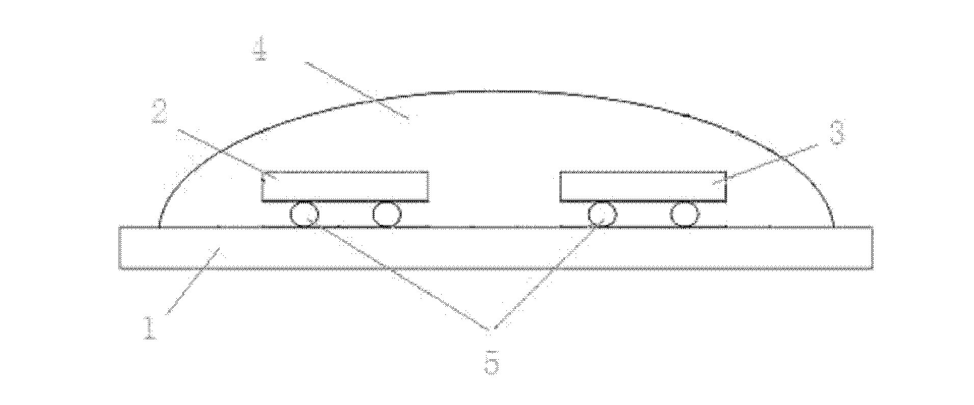
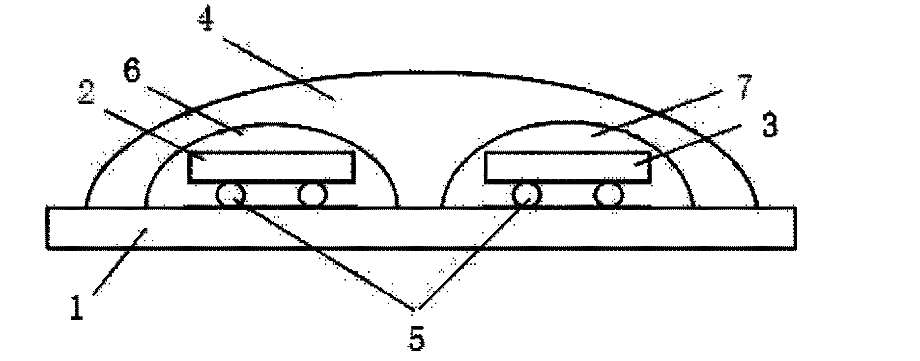
[0039] figure 1 For the schematic diagram of the LED packaging device of the embodiment of the present invention, please refer to figure 1 , it can be known that the LED packaging device of the embodiment of the present invention includes: a wafer 1 used as a substrate, an LED chip 2 and an LED chip 3 for generating different light emitting wavelengths when an electric current is applied, and the LED chip 2 and the LED chip 3 The lens layer 4 packaged in the same cavity is used to flip-chip the LED chip 2 and the LED chip 3 onto the flip-chip bump 5 of the wafer 1 .

[0040] figure 2 For the flow chart of the LED packaging method in the embodiment of the present invention, please refer to figure 2 :

[0041] S01, making flip-chip bumps 5 on wafer 1, LED chip 2, and LED chip 3, and flip-chip welding LED chip 2 and LED chip 3 on wafer 1;

[0042] S02 , the lens layer 4 made by molding method encapsulates the LED chips 2 and the LED chips 3 in the same cavity, and fixes the...


PUM


Abstract

The invention discloses a light-emitting diode (LED) packaging method, an LED packaging device, a light adjusting method and a light adjusting system. The LED packaging method comprises the following steps of: combining two or more than two LED chips which generate different fluorescence emission wavelengths into one group; mounting the group of LED chips on the same substrate; manufacturing a light-transmitting lens layer; and packaging the LED chips combined in one group in the same cavity through the light-transmitting lens layer. The LED packaging method, the LED packaging device, the light adjusting method and the light adjusting system, which can improve the white light rendering property and the light-mixing effect, realize light brightness, development and color temperature adjustment, overcome color spectrum defects and improve lighting effect, are provided through the technical scheme.

Description

technical field [0001] The invention relates to the technical field of LEDs, in particular to an LED packaging method, a packaging device, a light adjustment method and a system. Background technique [0002] Compared with traditional lighting sources, LED light-emitting devices have many significant advantages, such as lower power requirements, better driving characteristics, faster response speed, higher shock resistance, longer service life, green environmental protection, etc. Therefore, the market demand for LED light-emitting devices continues to grow, gradually replacing traditional lighting sources. [0003] For traditional white LED devices, the usual packaging method is to coat a single-color LED chip with a phosphor to mix light. This packaging light combination lacks the necessary light elements, resulting in low color rendering. In order to solve this problem, some people mix and coat several colors of phosphors on the single-color LED chip for light mixing. Al...

Claims


Application Information

Patent Timeline
IPC IPC(8): H01L33/00H01L25/075
CPCH01L2224/48091H01L2224/45124H01L2224/73265H01L2224/16225H01L2224/45144H01L2224/48227
Inventor 金鹏罗华杰
Owner CHINA COTRUN TECH
Learn More