
Mixed cascading type multilevel stored energy charging-discharging and voltage-equalizing circuit

A hybrid cascading and voltage-equalizing circuit technology, which is applied to systems that store electrical energy, electrical components, and conversion equipment that can be converted to DC without intermediate conversion. It can reduce the direct series-parallel, small jump and harmonic, and improve the system performance.

Active Publication Date: 2011-09-14
TSINGHUA UNIV
View PDF2 Cites 24 Cited by
  • Summary
  • Abstract
  • Description
  • Claims
  • Application Information

AI Technical Summary

Problems solved by technology

There are mainly resistance voltage equalization, switch resistance voltage equalization and voltage regulator tube voltage equalization methods, etc. These methods consume energy on resistors, and the efficiency of the voltage equalization circuit is relatively low.
The other is the energy transfer type voltage equalization method, which uses inductors, capacitors, transformers, etc. as energy transfer intermediaries to transfer excess energy from some monomers to other monomers. Transfer intermediary volume and cost are high
Moreover, the existing above-mentioned two types of methods are passively adjusted when the voltage is unbalanced, and the initiative is low.

Method used


Image

  • Mixed cascading type multilevel stored energy charging-discharging and voltage-equalizing circuit
  • Mixed cascading type multilevel stored energy charging-discharging and voltage-equalizing circuit
  • Mixed cascading type multilevel stored energy charging-discharging and voltage-equalizing circuit

Examples


Embodiment Construction

[0020] The present invention will be described in detail below in conjunction with the accompanying drawings and embodiments.

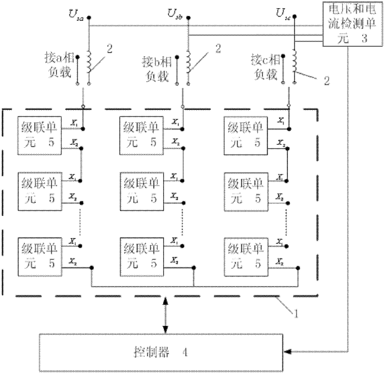
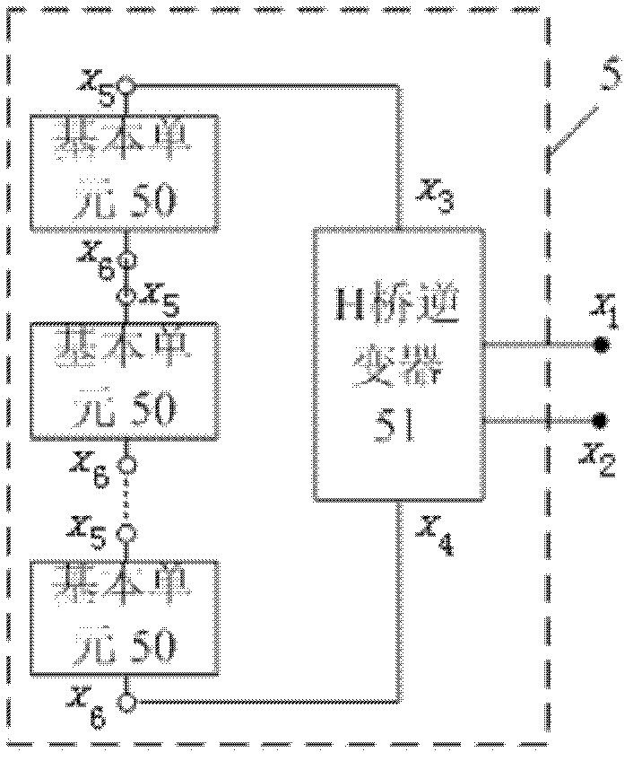
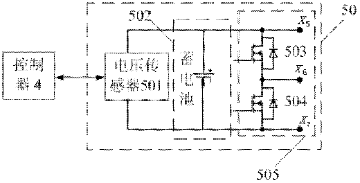
[0021] Such as figure 1 As shown, the present invention includes a multilevel converter 1, an inductor 2, a voltage and current detection unit 3 and a controller 4, wherein the multilevel converter 1 includes a three-phase circuit, and each phase circuit includes several stages connected in series Cascade unit 5, two connection terminals X for each cascade unit 5 1 、X 2 Respectively with the connection terminal X of the adjacent cascade unit 5 2 , the connection terminal X of the adjacent cascade unit 5 1 in series. The three-phase output terminal of the multilevel converter 1 is connected to the three-phase loads a, b and c to realize the discharge function, that is, supply power to the load; the three-phase input terminal U of the multilevel converter 1 sa , U sb and U sc They are respectively connected to an external grid through an inductor...


PUM


Abstract

The invention relates to a mixed cascading type multilevel stored energy charging-discharging and voltage-equalizing circuit, which is characterized by comprising a multilevel converter, inductors, a voltage and current detection unit and a controller, wherein the multilevel converter comprises a three-phase circuit, each phase circuit comprises a plurality of tandem cascading units, and two connectors of each cascading unit are respectively connected with connectors of the adjacent cascading unit in series; three-phase output ends of the multilevel converter are connected with loads and three-phase input ends of the multilevel converter are respectively connected with an external power grid by the inductors; and power-grid input sides of each inductor are respectively connected with the voltage and current detection unit, the voltage and current detection unit is used for transmitting detected power-grid voltage and current signals to the controller, and the controller carries out information interaction with the multilevel converter. In the circuit, a stored energy structure with a mixed structure of storage batteries and a super capacitor is adopted, thus decreasing direct series-parallel connection of stored energy units, and being simpler in circuit structure. The circuit can be widely applied to stored energy of electric systems, electric automobiles and other systems.

Description

technical field [0001] The invention relates to a topology structure of a multi-level energy storage charging and discharging controller, in particular to a hybrid cascaded multi-level energy storage charging and discharging and voltage equalizing circuit. Background technique [0002] Energy storage devices such as batteries and supercapacitors are increasingly used in power system energy storage and electric vehicles. The charge and discharge controller, voltage equalization and current equalization circuit in the energy storage device can improve the utilization rate of the energy storage device, avoid voltage equalization and current equalization problems caused by inconsistent monomer characteristics, and improve the life of the energy storage unit. [0003] At present, the charge and discharge of batteries and supercapacitors use a single power source to charge the entire energy storage device, and the charge and discharge controller controls the charging voltage and c...

Claims


Application Information

Patent Timeline
Patent Type & Authority Applications(China)
IPC IPC(8): H02M5/06H02J15/00H02M7/537
Inventor 郑泽东王奎李永东
Owner TSINGHUA UNIV
Learn More